
Splined connection

a technology of splined connection and lubricating surface, which is applied in the direction of couplings, gearings, hoisting equipment, etc., can solve the problems of long period of good lubrication of the surface of the connection region, and achieve the effects of preventing lubricant leakage, preventing ingress of dirt and ambient particles, and preventing obliqueness and radial displacemen

Inactive Publication Date: 2005-08-04
SCANIA CV AB
View PDF11 Cites 0 Cited by
  • Summary
  • Abstract
  • Description
  • Claims
  • Application Information

AI Technical Summary

Benefits of technology

[0007] One object of the present invention is to provide a splined connection whereby the connection region between hub and shaft comprises sealing means reliably preventing lubricant leaking out while at the same time preventing ingress of dirt and ambient particles. Another object is to prevent obliqueness and radial displacement between shaft and hub in the connection region.
[0008] These objects are achieved with the splined connection of the kind mentioned in the introduction which includes the elements disclosed herein. Two annular sealing elements are arranged in the connection so that each of them comes to continuous abutment against a contact surface of the shaft (the shaft being arranged radially inside) and a contact surface of the hub (the hub being arranged radially outside) ensures that the sealing elements completely fill and cover the radial clearance between the shaft and hub. There is thus assurance that the lubricant applied in the connection region between hub and shaft will not leak out. Supplying lubricant to the connection region between hub and shaft and fitting said sealing elements result in a long period of good lubrication of the surfaces of the connection region. At the same time, the sealing elements prevent ingress of dirt and ambient particles into the connection region. The two annular sealing elements also serve as spacers which tend to maintain the centred position of the shaft relative to the hub. As the annular elements completely filling the radial gap between shaft and hub are at a distance from one another, they effectively counteract any angling of the shaft relative to the hub.
[0009] According to a preferred embodiment of the invention, at least one of said annular seals comprises an elastic material. An elastic material ensures a good seal between shaft and hub even when axial movements between shaft and hub occur. However, the elastic material needs rigidity such as to provide stable support surfaces which effectively counteract obliqueness and radial displacement of the hub relative to the shaft. With advantage, at least one of said annular seals is an O-ring. O-rings are inexpensive to procure and have good sealing characteristics. Suitably dimensioned O-rings which also have suitable material characteristics provide stable support surfaces.
[0010] According to another preferred embodiment of the invention, at least one of said contact surfaces on the shaft is situated at a substantially constant radial distance from an axis of rotation of the splined connection. Said contact surface therefore exhibits a circular shape and can be fitted with an elastic O-ring so that the latter's inner radial surface will abut with a specific pressure round the surface of the whole shaft. The result is an optimum seal. The contact surface of the shaft may be situated level with the shaft grooves. The shaft will thus be relatively uncomplicated in shape and can be manufactured at relatively low cost. Correspondingly, at least one of said contact surfaces of the hub may be situated at a substantially constant radial distance from said axis of rotation. The contact surface of the hub therefore exhibits a circular shape, and an elastic O-ring can be fitted inside the hub so that its outer radial surface will abut with a specific pressure round the inside surface of the whole hub. The result is a substantially optimum seal. The contact surface of the hub may be situated level with the hub grooves. The hub will thus be relatively uncomplicated in shape and can be manufactured at relatively low cost.
[0011] According to another preferred embodiment of the invention, at least one of said sealing elements is adapted to being fitted in an annular space which is defined not only by said contact surface of the shaft and said contact surface of the hub but also by sidewalls which delineate the width of the annular space. Said sidewalls prevent lateral movements of the sealing elements even if there are axial movements between shaft and hub. One such sidewall may be defined by end surfaces of the shaft ridges. The shaft ridges preferably do not extend right up to an end surface of the shaft. The shaft may thus have a contact surface adjacent to the ridge end surfaces which thus constitute sidewalls preventing axial movement of sealing elements in an axial direction. Alternatively, the shaft ridges may comprise a common break at one point so that a circumferential recess is created. Such a recess has on both sides of it sidewalls defined by the ridge end surfaces. One of said sidewalls may be defined by the hub ridge end surfaces. The hub ridges may be made shorter than the width of the hub. The hub may thus have contact surfaces adjacent to the ridge end surfaces which thus define a sidewall preventing axial movement of the sealing element. Alternatively the hub ridges may comprise a break at a common point so as to create a circumferential recess. Such a recess has on both sides of it sidewalls defined by the ridge end surfaces.
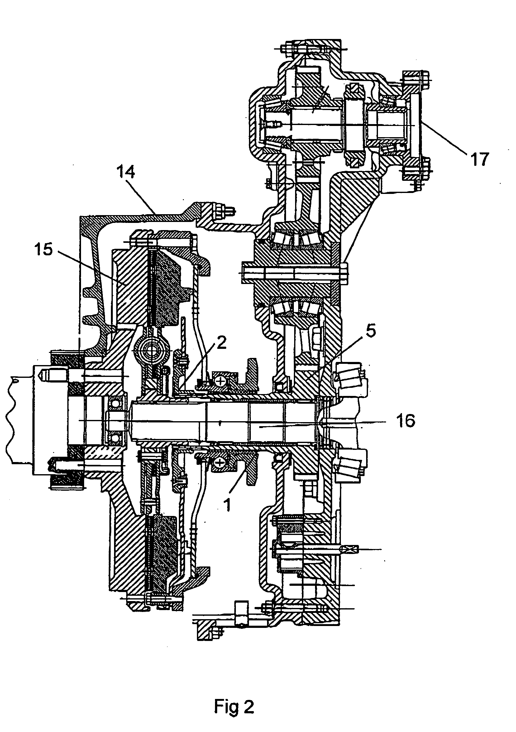
[0012] According to another preferred embodiment of the invention, the splined connection is arranged as a transmission element in a power takeoff of a vehicle. In that case the location of the splined connection may make it difficult to supply lubricant after assembly. Said sealing elements situated at a distance from one another on different sides of the connection region result in completely sealed enclosing of the connection region. This means that the lubricant originally supplied to the connection region can be effectively retained. In addition, the two sealing elements provide support surfaces situated at a distance from one another so that obliqueness and radial displacement of the shaft relative to the hub are counteracted. The splined connection may be arranged in a housing which contains a clutch of the vehicle. Such a housing makes it very difficult to supply lubricant to the connection region. At the same time, plenty of dust and particles occurs within such a housing. Said sealing elements retain lubricant in the connection region while at the same time effectively preventing ingress of particles into the connection region.

Problems solved by technology

Supplying lubricant to the connection region between hub and shaft and fitting said sealing elements result in a long period of good lubrication of the surfaces of the connection region.

Method used


Image

  • Splined connection
  • Splined connection
  • Splined connection

Examples


Embodiment Construction

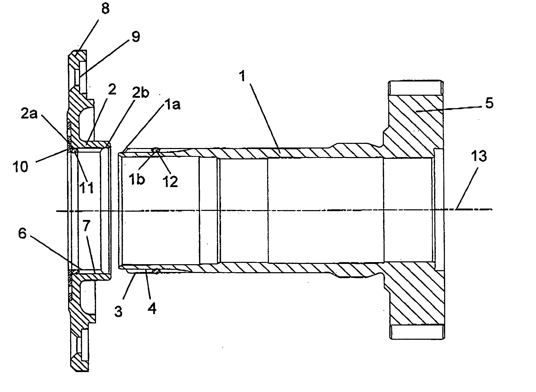
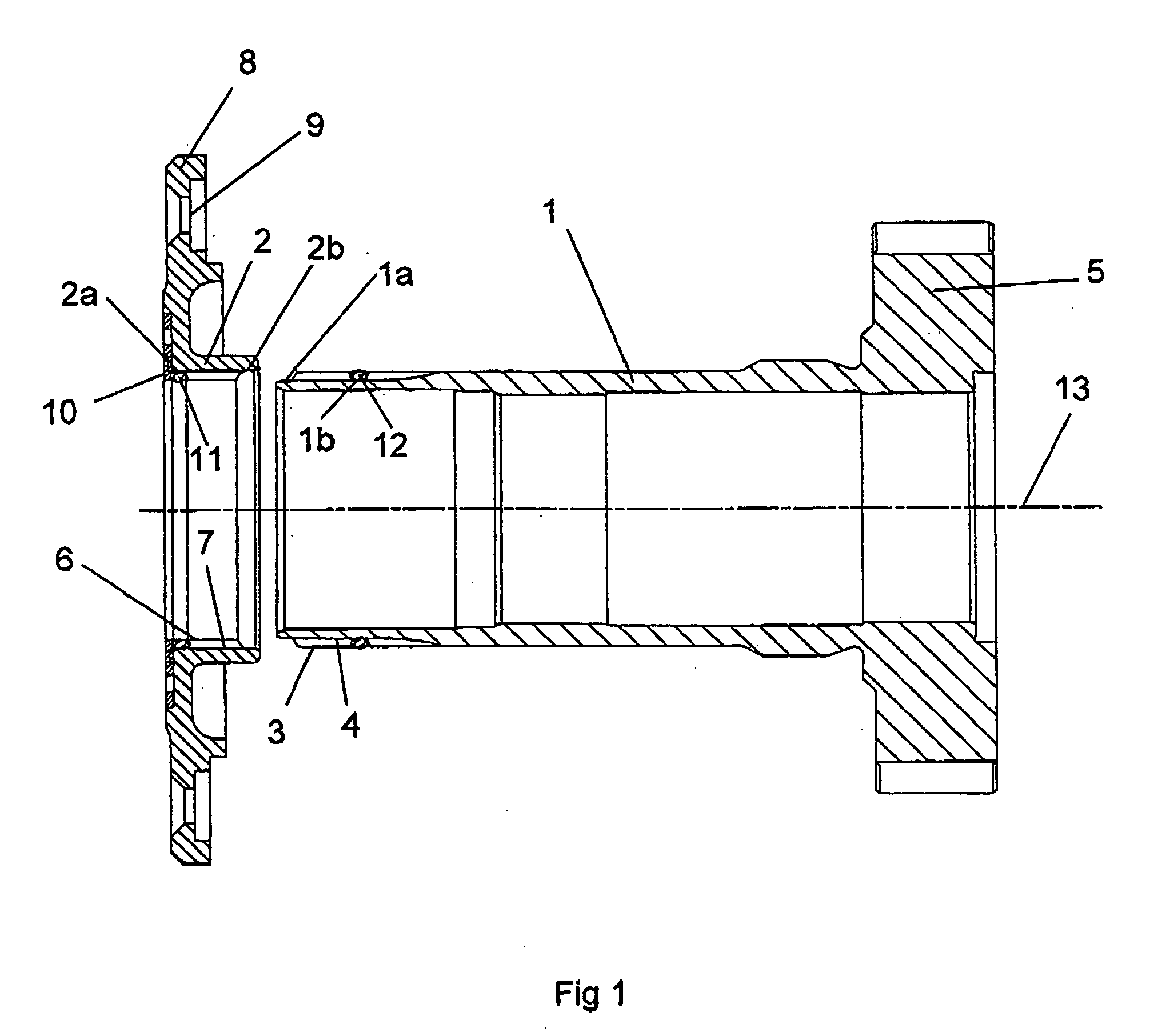
[0016]FIG. 1 depicts a splined connection in an unassembled state. The splined connection comprises mainly two parts, namely a shaft 1 and a hub 2. The shaft 1 has at one end splining, which in a conventional manner comprises a multiplicity of longitudinal protruding ridges 3 and intermediate grooves 4 between the ridges. The ridges 3 and grooves 4 are usually arranged at uniform intervals round the circumference of the shaft 1. At an opposite end, the shaft 1 comprises a firmly attached gearwheel 5. In the case depicted, the shaft 1 is hollow. The splined connection comprises a hub 2 which has internally arranged splining. The splining of the hub is likewise provided in a conventional manner with a multiplicity of ridges 6 and intermediate grooves 7. The ridges 6 and grooves 7 of the hub are adapted to being fitted in engagement with the ridges 3 and grooves 4 of the shaft so as to provide a connection causing the shaft 1 and hub 2 to rotate together in the splined connection regio...


PUM


Abstract

A splined connection comprises a shaft with longitudinal radially outwardly protruding ridges and intermediate grooves, a hub provided with correspondingly shaped ridges and intermediate grooves and is adapted to being fitted in engagement with the shaft ridges and grooves to provide between the shaft and the hub a connection region causing the shaft and hub to rotate together. A sealing arrangement adapted to close off the connection region. The sealing arrangement comprises two annular sealing elements applied at an axial distance from one another and adjacent to the connection region so that the sealing elements are each in continuous contact with a surface of the shaft around the whole of their inner radial surface and in continuous contact with a surface of the hub around the whole of their outer radial surface.

Description

BACKGROUND TO THE INVENTION, AND STATE OF THE ART [0001] The present invention relates to a splined connection and particularly to elements which orient the shaft and hub connected and also seal that connection. [0002] Splined connections are used in various applications in connection with torque transmission. Splined connections are particularly advantageous in cases where axial mobility between components is required. A splined connection usually comprises a shaft-shaped element provided with longitudinal protruding ridges and intermediate grooves, and a hub-shaped element provided with correspondingly shaped ridges and intermediate grooves and intended to be fitted in engagement with the ridges and grooves of the shaft so that a connection region causing the shaft and hub to rotate together is formed between them. [0003] An example of such an application is in connection with transmission of torque from an engine to a power takeoff of a vehicle. In such cases the power takeoff ma...

Claims


Application Information

Patent Timeline
Patent Type & Authority Applications(United States)
IPC IPC(8): F16D1/10F16D1/06F16H57/02
CPCF16D1/101Y10T403/7026Y10T74/19893F16D2300/06
Inventor GARDIN, MICHAEL
Owner SCANIA CV AB
Learn More