Ram for metal can shaper

a metal can and ram technology, applied in the direction of shaping tools, forging/pressing/hammering apparatus, forging/hammering/pressing machines, etc., can solve the problems of tube lubing process having continual problems, coupling wear out, and self-must be strong enough to withstand, so as to reduce friction, reduce drag, and increase life. the effect of length

Active Publication Date: 2011-09-15
FARNHAM ENTERPRISES
View PDF2 Cites 0 Cited by
  • Summary
  • Abstract
  • Description
  • Claims
  • Application Information

AI Technical Summary

Benefits of technology

[0002]Beverages are commonly served in aluminum and metal cans which are made at the pace of more than one million per day. They are generally formed from two pieces: a top (which generally has a tab for opening the beverage) which is generally affixed to a bottom after it is filled with a liquid substance such as a beer or soda. It is desirable to make the can as thin as possible, to reduce material and shipping costs. However, the can itself has to be strong enough to withstand both internal and external pressures. To do so the cylinder section of the can has many curves in its top and bottom to make the can more rigid and able to withstand the internal and external pressures created by internal gases and external axle loads created by stacking and handling. Necking down the top of the container requires less metal to form the top, further reducing the cost of the container and the expense to the end user.
[0004]The necker cylinders have many various components. The key components are the cylinder “bushing” and the ram or piston. The bushing and the ram, combined are currently a liquid tight cylinder with seals at opposing ends to prevent lubricant leaks while the piston moves back and forth at high speeds during the necking process. The piston is a round cylinder that rides in a brass or steel bushing. One end of the piston has two wheels that follow a rail on a stationary cam that has a curve in the rail track to make the piston move back and forth as the turret turns. To prevent the round piston from spinning in the bushing, there is an internal key and keyway that also allows the cam followers to stay indexed to the rail of the cam and prevents centrifugal force from turning the piston during high speed operation.
[0008]Numerous attempts have been made to try and solve these problems within the art. One design is the square ram assembly, which tries to eliminate the lubrication problems and key way and weight as well. This design uses a rectangular ram and a solid bushing with a rectangular opening to accept the ram. Both made of aluminum to address the weight issue and by applying a Teflon-ceramic coating on the friction surfaces to address the lubrication problem. This solution only works for a short period of time before the coating breaks down and fails requiring rebuild. Also the tooling adaptors are added to the ram because it is made of soft aluminum which breaks and wears rapidly. This only increases the number of assembly parts and cost of such parts. The rectangular ram does address the key way issue but the points in the corners cause pinch points and wear edges as well. This only creates another inherent problem or break down starting point, thus not a solid solution.
[0009]Accordingly, it is the object of the present invention to provide a lubricant free assembly, with increased life span, less drag and less friction.
[0011]The present invention relates generally to ram assemblies, and in particular to a lubricant-free, low drag, low friction ram assembly with increased life span.

Problems solved by technology

However, the can itself has to be strong enough to withstand both internal and external pressures.
These old style ram assemblies are lubricated by hand in a very time consuming process that required regular line shut down time to assure the pistons are properly lubricated.
This tube lubing process has continual problems because the tubes are connected to special couplings to accommodate the spinning of the turrets.
These couplings wear out and allow grease to contaminate thousands of cans before the problem is detected.
Another problem is the oil seals at the end of the bushings.
These oil seals wear out and cause contamination as well and the shut down time is even greater.
The internal key and key way is also problematic.
They often break down or loosen, destroying the ram assembly and commonly the oil seals as well.
Production is again interrupted and damage to the cam and the machine must be repaired.
When a cylinder malfunctions the cans are contaminated and must be scrapped.
The shut down time to repair these cylinders costs manufacturers $10,000 or more per hour in lost revenues.
This is a very time consuming process and very costly as well due to the 8 to 16 hours required to replace these cylinders.
These shut downs cost on average more than $100,000.00 each time in loss of production plus the cost of rebuilding.
The weight is another inherent problem.
These cylinder assemblies can weigh in excess of 20 pounds each requiring a tremendous amount of energy to turn the turrets due to the fact that the assemblies are made of brass and steel.
This solution only works for a short period of time before the coating breaks down and fails requiring rebuild.
This only increases the number of assembly parts and cost of such parts.
The rectangular ram does address the key way issue but the points in the corners cause pinch points and wear edges as well.
This only creates another inherent problem or break down starting point, thus not a solid solution.

Method used


Image

  • Ram for metal can shaper
  • Ram for metal can shaper
  • Ram for metal can shaper

Examples


Embodiment Construction

[0021]The following detailed description is of the best currently contemplated modes of carrying out the invention. The description is not to be taken in a limiting sense, but is made merely for the purpose of illustrating the general principles of the invention, since the scope of the invention is best defined by the appended claims.

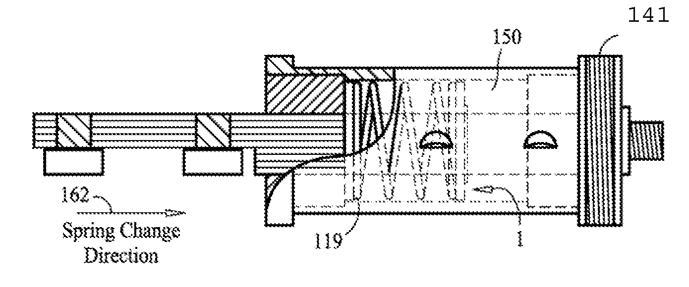
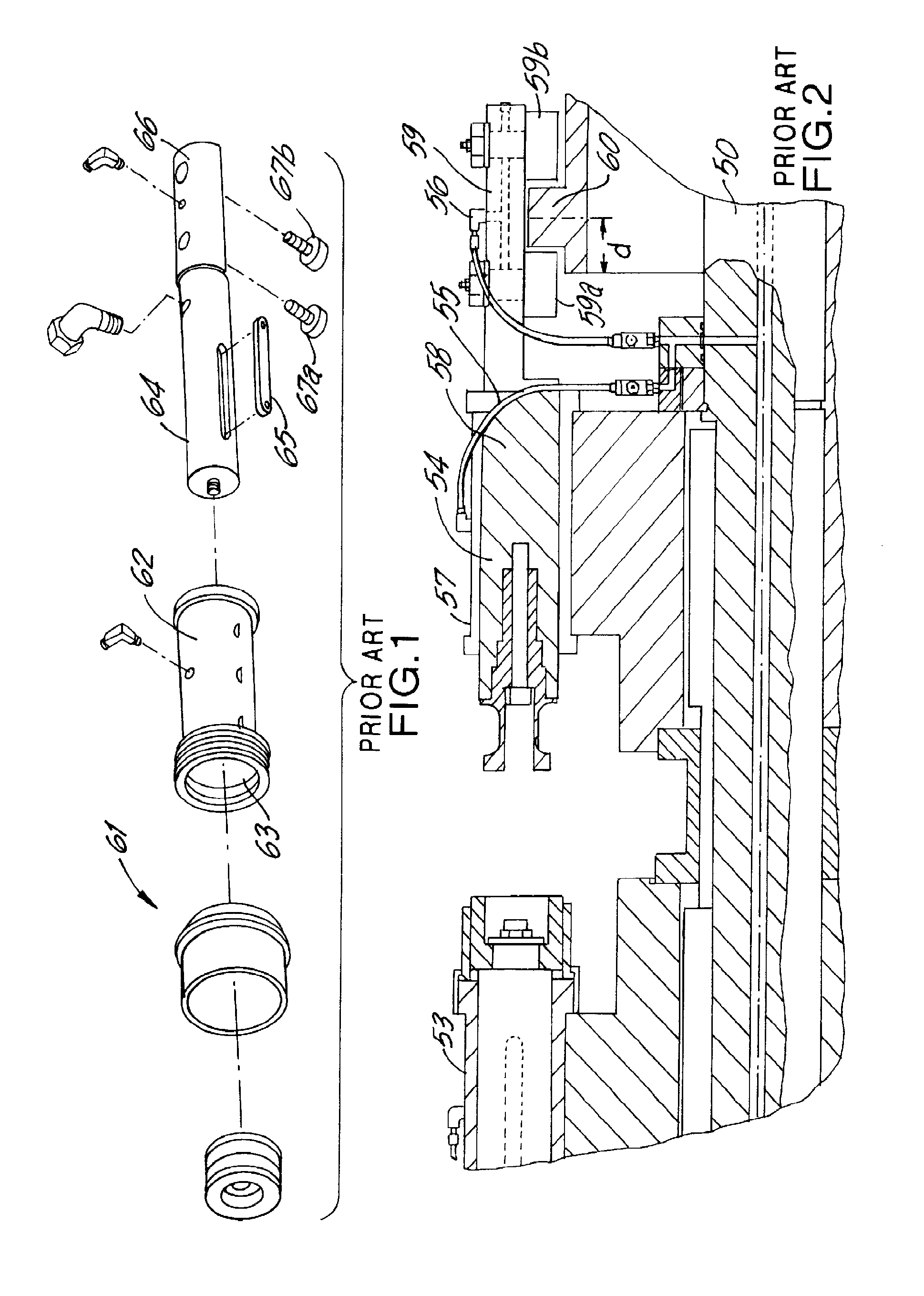
[0022]FIG. 1 depicts a typical ram assembly 61. The bushing 62 has a round bore 63 in which the ram slides in. The ram 64 has a key 65 that slides in a key way (not shown) The tail portion 66 has two cam followers (67a and 67b). FIG. 2 depicts a cross sectional view of a portion of a BELVAC metal can forming machine. A central shaft 50 is motor driven and rotates. The turrets are fixed to the shaft and rotate with it. Series of rams are mounted to the turrets. A series of lubrication tubes 55 leads to a lubrication nozzles 56. The ram assembly 54 includes a fixed bushing 57 having a round bore and a ram 58. The tail portion 59 of the ram 58 carries two ...


PUM

PropertyMeasurementUnit
timeaaaaaaaaaa
external pressuresaaaaaaaaaa
pressuresaaaaaaaaaa

Abstract

An apparatus for forming a two-piece can comprising: a cylindrical housing, the cylindrical housing having a first end and a second end; a first round bushing having a longitudinal rectangular bore and received in the first end; a second round bushing having a longitudinal rectangular bore and received in the second end; a substantially cornerless rectangular ram which slides in the longitudinal rectangular bore of the first round bushing and the longitudinal rectangular bore of the second round bushing; a spring interposed between the first round bushing and the second round bushing and surrounding the substantially rectangular ram.

Description

[0001]This is a continuation of co-pending patent application Ser. No. 11 / 927,842 filed Oct. 30, 2007 and entitled “Ram for Metal Can Shaper”, the entire contents of which are incorporated herein by reference. The present invention is in relation to the machines used to form or “neck” the end of the can cylinder as part of a two piece can process.[0002]Beverages are commonly served in aluminum and metal cans which are made at the pace of more than one million per day. They are generally formed from two pieces: a top (which generally has a tab for opening the beverage) which is generally affixed to a bottom after it is filled with a liquid substance such as a beer or soda. It is desirable to make the can as thin as possible, to reduce material and shipping costs. However, the can itself has to be strong enough to withstand both internal and external pressures. To do so the cylinder section of the can has many curves in its top and bottom to make the can more rigid and able to withsta...

Claims


Application Information

Patent Timeline
Patent Type & Authority Applications(United States)
IPC IPC(8): B21D51/26
CPCB21D51/2638B21D51/2615
Inventor FARNHAM, TIMOTHY J.
Owner FARNHAM ENTERPRISES
Why Eureka
Try Eureka