Lubricant sealing structure for gear coupling

a technology of lubricant sealing and gear coupling, which is applied in the direction of engine seals, mechanical devices, engine components, etc., can solve the problems of lubricant leakage, instability of work platforms, and lubricant around the tower, so as to improve the flexibility of cloth-inserted rubber and prevent lubricant leakage

Inactive Publication Date: 2014-09-02
MITSUBISHI HEAVY IND LTD
View PDF10 Cites 0 Cited by
  • Summary
  • Abstract
  • Description
  • Claims
  • Application Information

AI Technical Summary

Benefits of technology

[0020]In view of the problems of the related art, it is an object of the present invention is to provide a lubricant sealing structure for a gear coupling, the sealing structure being capable of firmly preventing the leaking of the lubricant due to movements such as vibration in the axial and radial directions of the drive shaft inside the gear coupling.
[0048]Further, the rubber member is provided at least one of between the first fixing member and the cover plate and between the second fixing member and the one of the drive shaft and the stopper plate. This enhances the flexibility of the cloth-inserted rubber to the movement in the axial and radial direction, and thus, the sealing effect on the plane perpendicular to the axial direction can be firmly achieved and the leaking of the lubricant can be prevented.

Problems solved by technology

With use of the sealing member for the lubricant, if the surface of the iron band 41 fixed to the top surface of the drive shaft 10 looses its contact pressure due to vibration or causes sliding, the sealing effect of the cloth-inserted rubber sheet 21 becomes insufficient, often causing the lubricant to leak.
The leaking of the lubricant leads to instability of a work platform and leaking of the lubricant around the tower 18.

Method used


Image

  • Lubricant sealing structure for gear coupling
  • Lubricant sealing structure for gear coupling
  • Lubricant sealing structure for gear coupling

Examples


first preferred embodiment

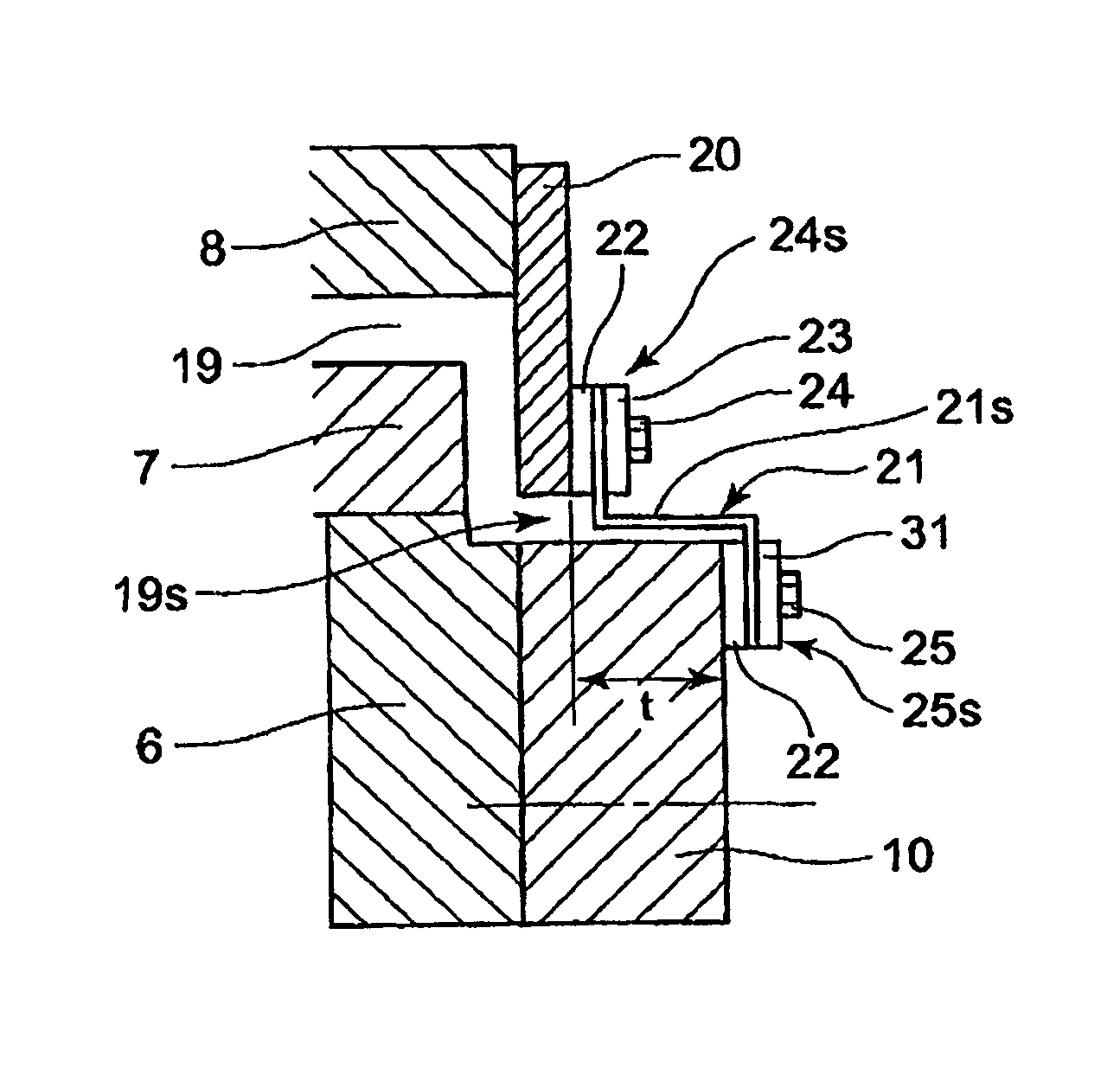
[0067]FIG. 1 is an enlarged view of a section Z of FIG. 6, illustrating a structure of a storage part for the lubricant in relation to a first preferred embodiment of the present invention.

[0068]The gear coupling 07 includes the outer ring 7 formed with internal teeth and the drive shaft 10 formed with external teeth to mesh with the internal teeth of the outer ring 7. Specifically, the external teeth of the second inner ring 6 mesh with the internal teeth and the drive shaft 10 is fixed to the second inner ring 6 via the bolts 16. The gearing coupling 07 also includes the bearing sleeve 8.

[0069]The lubricant such as grease oil is stored in the interior space 19s which includes the inside space 12 and the outside space of the outer ring 7.

[0070]The cover plate 20 is fixed to the side of the bearing sleeve 8 by a plurality of bolts (unshown).

[0071]A fixing member 24s fixes the cover plate 20 fixed to on a side of the bearing sleeve 8. Another fixing member 25s is disposed a side of t...

second preferred embodiment

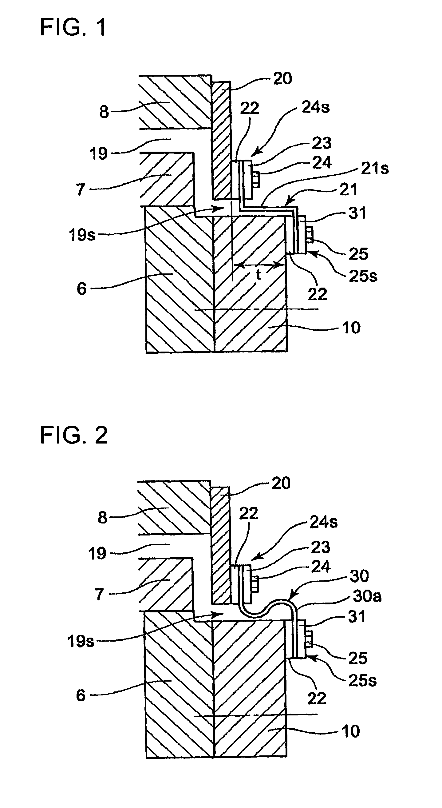
[0084]FIG. 2 is an enlarged view of a section Z of FIG. 6, illustrating a structure of a storage part for the lubricant in relation to a second preferred embodiment of the present invention.

[0085]In the second preferred embodiment, the sealing member is a cloth-inserted rubber 30. The cloth-inserted rubber extends inwardly in the radial direction of the drive shaft 10 from the fixing member 24s on the cover plate 20 of the bearing sleeve 8, then the cloth-inserted rubber is bent to extend in the axial direction of the drive shaft 10 while curving in an S-shape to form a curved part 30a, and then bent again to extend inwardly in the radial direction to reach the fixing member 25s. In other words, the cloth-inserted rubber 30 extends inwardly in the radial direction from the fixing member 24s on the cover plate, curves in an S-shape to extend in the axial direction, and then is bent to extend inwardly in the radial direction to reach the fixing member 25s on the side of the drive shaf...

third preferred embodiment

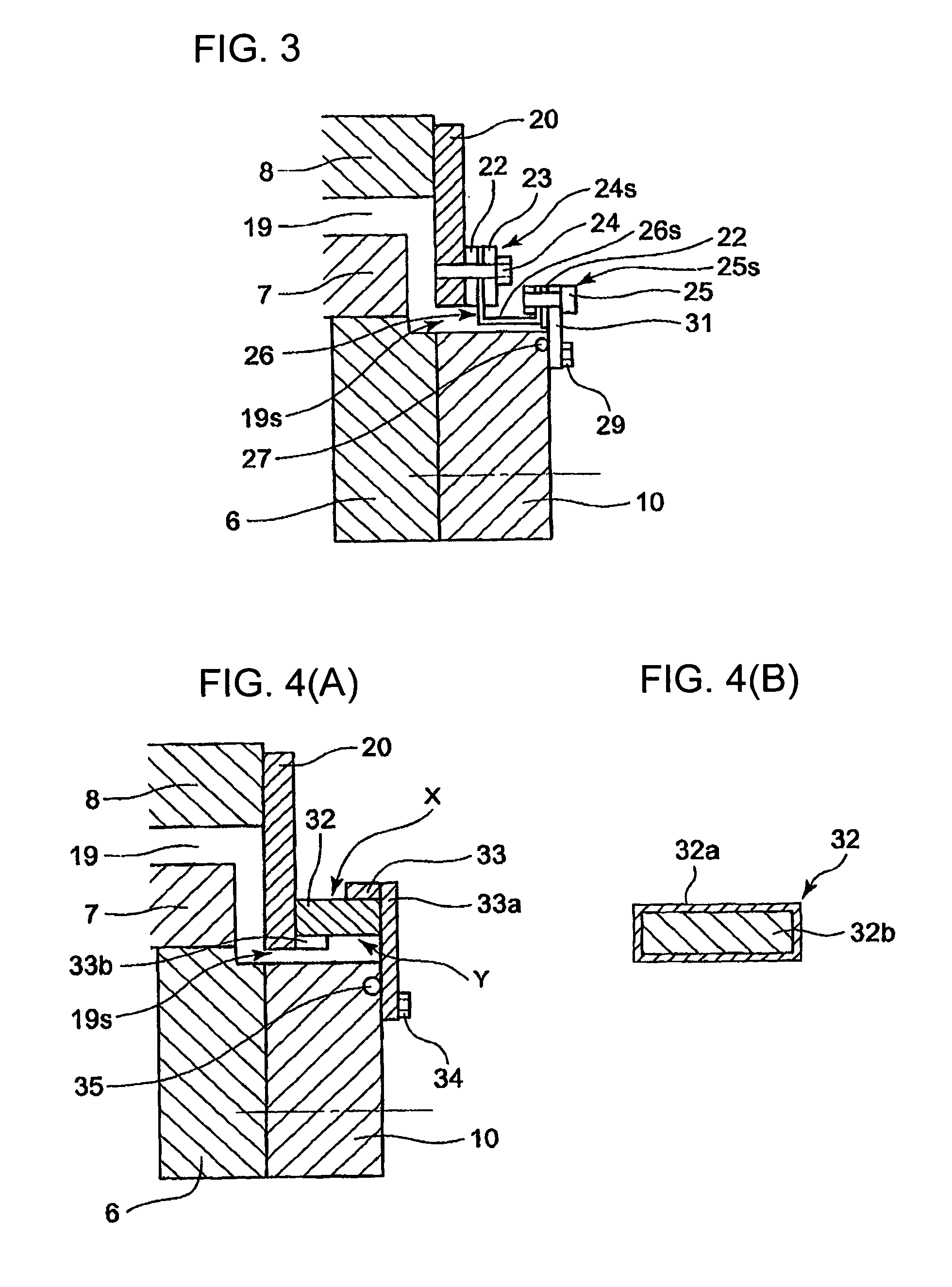
[0088]FIG. 3 is an enlarged view of a section Z of FIG. 6, illustrating a structure of a storage part for the lubricant in relation to a third preferred embodiment of the present invention.

[0089]According to the third preferred embodiment, the fixing member 24s on the cover plate 20 fixed to the side of the bearing sleeve 8 and the fixing member on the side of the drive shaft 10 are displaced in the radial direction and also displaced in the axial direction of the drive shaft 10 with a prescribed distance from each other. The fixing member 25s on the drive shaft 10 side is positioned outwardly in the radial direction with respect to the drive shaft 10. The fixing member 25s is secures on one end of the cloth-inserted rubber 26 to the stopper plate 31 extending outwardly in the radial direction of the drive shaft 10.

[0090]The fixing member 24s has the same structure as that of the first preferred embodiment (FIG. 1).

[0091]The sealing member is the cloth-inserted rubber 26 made from a...


PUM


Abstract

Disclosed is a lubricant sealing structure for a gear coupling, which can firmly prevent the leaking of the lubricant due to vibration or the like in the axial and radial directions inside the gear coupling. A sealing member is a cloth-inserted rubber 21 having flexibility. The cloth-inserted rubber 21 has a first end being fixed to a fixing member 24s on a cover plate 20 mounted on a side of an outer ring 7 and a second end being fixed to another fixing member 25s on a side of the drive shaft 10 in liquid tight manner in the axial direction of a drive shaft 10. Each of the first and second ends of the cloth-inserted rubber 21 has a face extending in a direction that is perpendicular to the axial direction. The cloth-inserted rubber 21 seals the lubricant at the face of said each of the first and second ends.

Description

TECHNICAL FIELD[0001]The present invention relates to a lubricant sealing structure for a gearbox or the like of a wind turbine. The lubricant sealing structure includes a gear coupling having an outer ring formed with internal teeth and a drive shaft formed with external teeth meshing with the internal teeth of the outer ring. The gear coupling has an interior space with a lubricant storage part for lubricant such as oil and grease. The lubricant storage space is sealed by a sealing member disposed between the outer ring and the drive shaft to prevent the lubricant from leaking.BACKGROUND ART[0002]FIG. 6 is a schematic sectional view taken along a shaft center of a drive mechanism of a wind turbine. In FIG. 6, a plurality of blades (normally three to five blades) are rotatably mounted on a rotor head 3 via a bearing 2. The rotation of the blades 1 are transmitted to the rotor head 3. A first inner ring 5 is connected to the rotor head 4 via a plurality of bolts 4. The rotation of t...

Claims


Application Information

Patent Timeline
Patent Type & Authority Patents(United States)
IPC IPC(8): F16J15/02
CPCF16J15/52
Inventor TAKAHASHI, FUMIHARUYANO, AKIHIKOSHODA, KATSUHIKOMIYAKE, HISAOKOGA, SHIN
Owner MITSUBISHI HEAVY IND LTD
Why Eureka
Try Eureka