Lubricant sealing structure for gear coupling
a technology of lubricant sealing and gear coupling, which is applied in the direction of engine seals, mechanical devices, engine components, etc., can solve the problems of lubricant leakage, instability of work platforms, and lubricant around the tower, so as to improve the flexibility of cloth-inserted rubber and prevent lubricant leakage
- Summary
- Abstract
- Description
- Claims
- Application Information
AI Technical Summary
Benefits of technology
Problems solved by technology
Method used
Image
Examples
first preferred embodiment
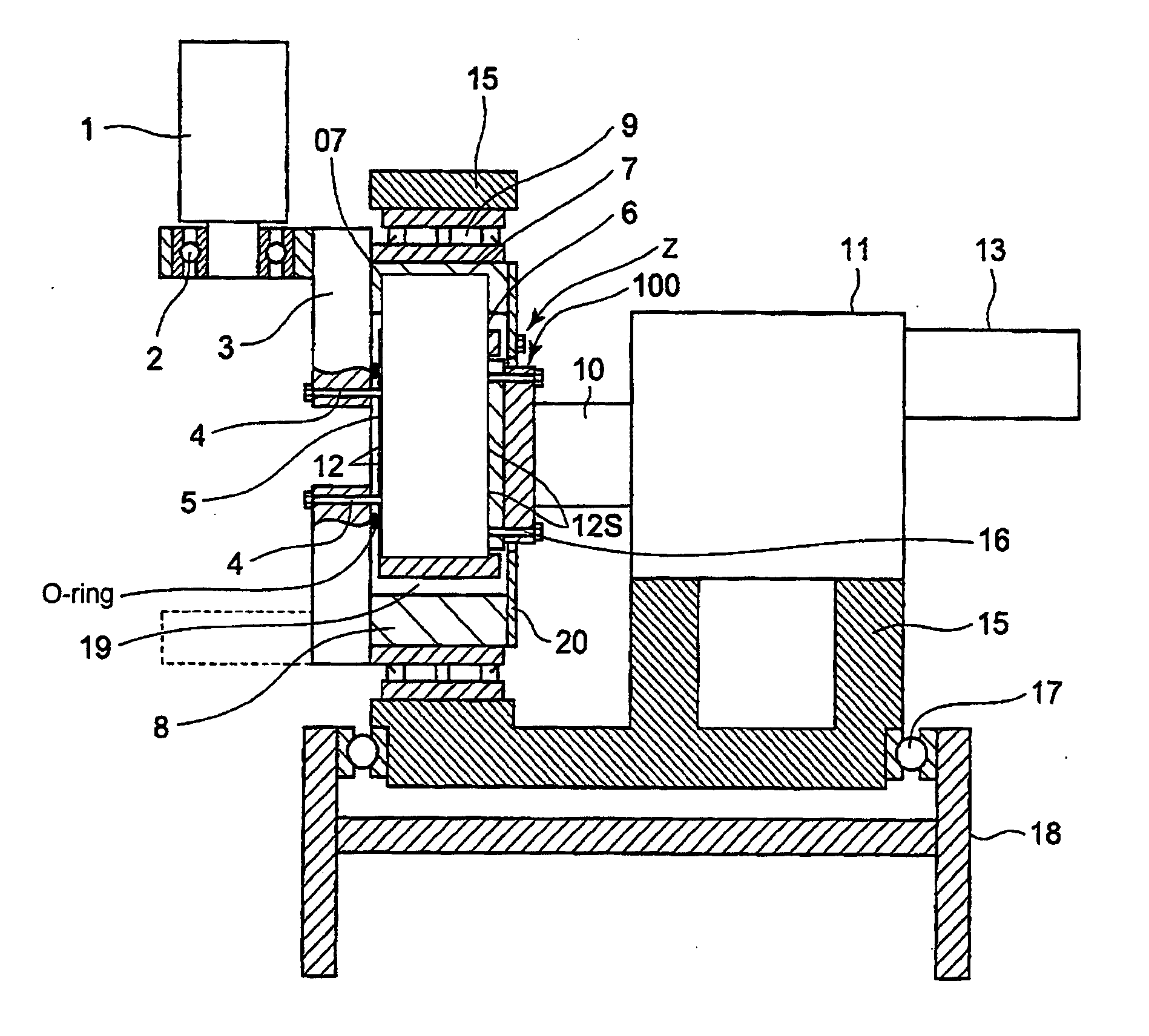
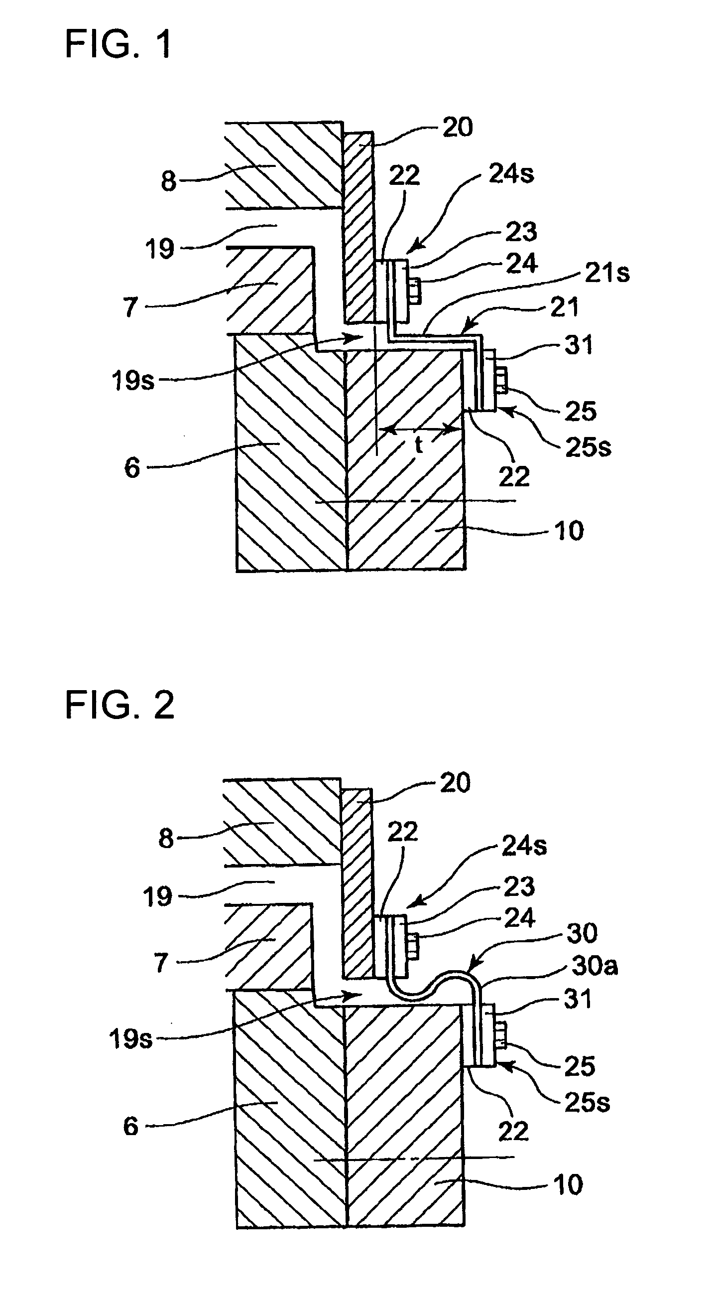
[0067]FIG. 1 is an enlarged view of a section Z of FIG. 6, illustrating a structure of a storage part for the lubricant in relation to a first preferred embodiment of the present invention.
[0068]The gear coupling 07 includes the outer ring 7 formed with internal teeth and the drive shaft 10 formed with external teeth to mesh with the internal teeth of the outer ring 7. Specifically, the external teeth of the second inner ring 6 mesh with the internal teeth and the drive shaft 10 is fixed to the second inner ring 6 via the bolts 16. The gearing coupling 07 also includes the bearing sleeve 8.
[0069]The lubricant such as grease oil is stored in the interior space 19s which includes the inside space 12 and the outside space of the outer ring 7.
[0070]The cover plate 20 is fixed to the side of the bearing sleeve 8 by a plurality of bolts (unshown).
[0071]A fixing member 24s fixes the cover plate 20 fixed to on a side of the bearing sleeve 8. Another fixing member 25s is disposed a side of t...
second preferred embodiment
[0084]FIG. 2 is an enlarged view of a section Z of FIG. 6, illustrating a structure of a storage part for the lubricant in relation to a second preferred embodiment of the present invention.
[0085]In the second preferred embodiment, the sealing member is a cloth-inserted rubber 30. The cloth-inserted rubber extends inwardly in the radial direction of the drive shaft 10 from the fixing member 24s on the cover plate 20 of the bearing sleeve 8, then the cloth-inserted rubber is bent to extend in the axial direction of the drive shaft 10 while curving in an S-shape to form a curved part 30a, and then bent again to extend inwardly in the radial direction to reach the fixing member 25s. In other words, the cloth-inserted rubber 30 extends inwardly in the radial direction from the fixing member 24s on the cover plate, curves in an S-shape to extend in the axial direction, and then is bent to extend inwardly in the radial direction to reach the fixing member 25s on the side of the drive shaf...
third preferred embodiment
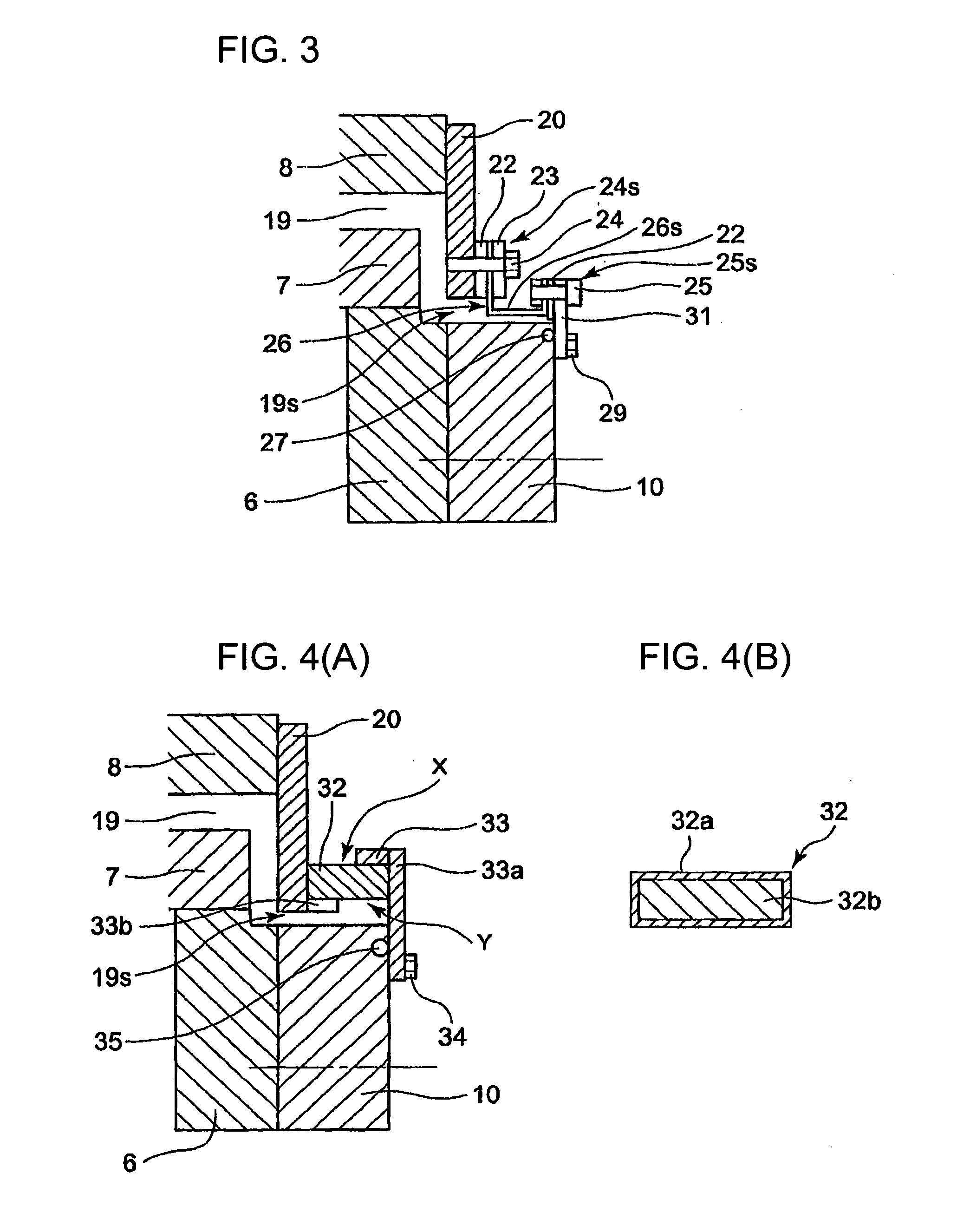
[0088]FIG. 3 is an enlarged view of a section Z of FIG. 6, illustrating a structure of a storage part for the lubricant in relation to a third preferred embodiment of the present invention.
[0089]According to the third preferred embodiment, the fixing member 24s on the cover plate 20 fixed to the side of the bearing sleeve 8 and the fixing member on the side of the drive shaft 10 are displaced in the radial direction and also displaced in the axial direction of the drive shaft 10 with a prescribed distance from each other. The fixing member 25s on the drive shaft 10 side is positioned outwardly in the radial direction with respect to the drive shaft 10. The fixing member 25s is secures on one end of the cloth-inserted rubber 26 to the stopper plate 31 extending outwardly in the radial direction of the drive shaft 10.
[0090]The fixing member 24s has the same structure as that of the first preferred embodiment (FIG. 1).
[0091]The sealing member is the cloth-inserted rubber 26 made from a...
PUM
 Abstract
Description
Claims
Application Information
 - R&D
- Intellectual Property
- Life Sciences
- Materials
- Tech Scout
- Unparalleled Data Quality
- Higher Quality Content
- 60% Fewer Hallucinations
Browse by: Latest US Patents, China's latest patents, Technical Efficacy Thesaurus, Application Domain, Technology Topic, Popular Technical Reports.
© 2025 PatSnap. All rights reserved.Legal|Privacy policy|Modern Slavery Act Transparency Statement|Sitemap|About US| Contact US: help@patsnap.com


