
Turbocharger

a turbocharger and turbocharger technology, applied in the direction of machines/engines, mechanical devices, liquid fuel engines, etc., can solve the problems of increasing production costs, reducing supercharge efficiency, increasing machining costs, etc., and achieves excellent effects and advantages, improve supercharge efficiency, and reduce production costs

Active Publication Date: 2010-12-16
IHI CORP
View PDF16 Cites 1 Cited by
  • Summary
  • Abstract
  • Description
  • Claims
  • Application Information

AI Technical Summary

Benefits of technology

[0019]A turbocharger of the invention can exhibit excellent effects and advantages. Provision of the seal plate in the form of press-fit plate can improve the supercharging efficiency and reduce the production cost. By the structure of the oil sump arranged between the oil thrower and oil-thrower facing part, the oil sump can receive the lubricant flowed out from the bearing portion to instantly discharge the same through the oil discharge openings, thus preventing the lubricant from leaking to the impeller.

Problems solved by technology

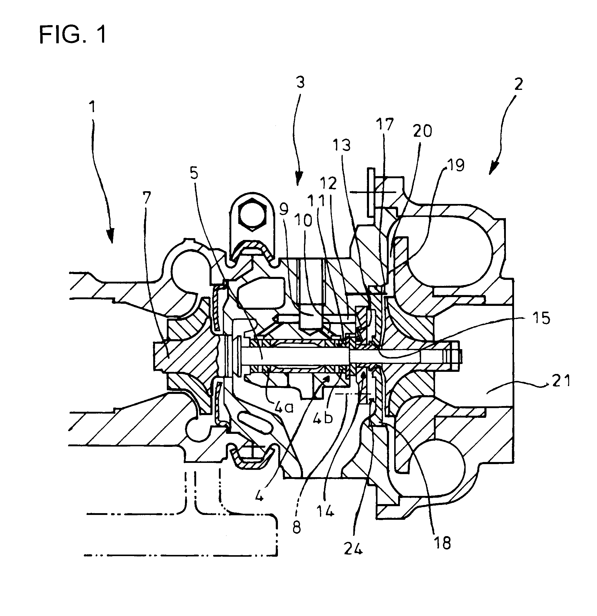
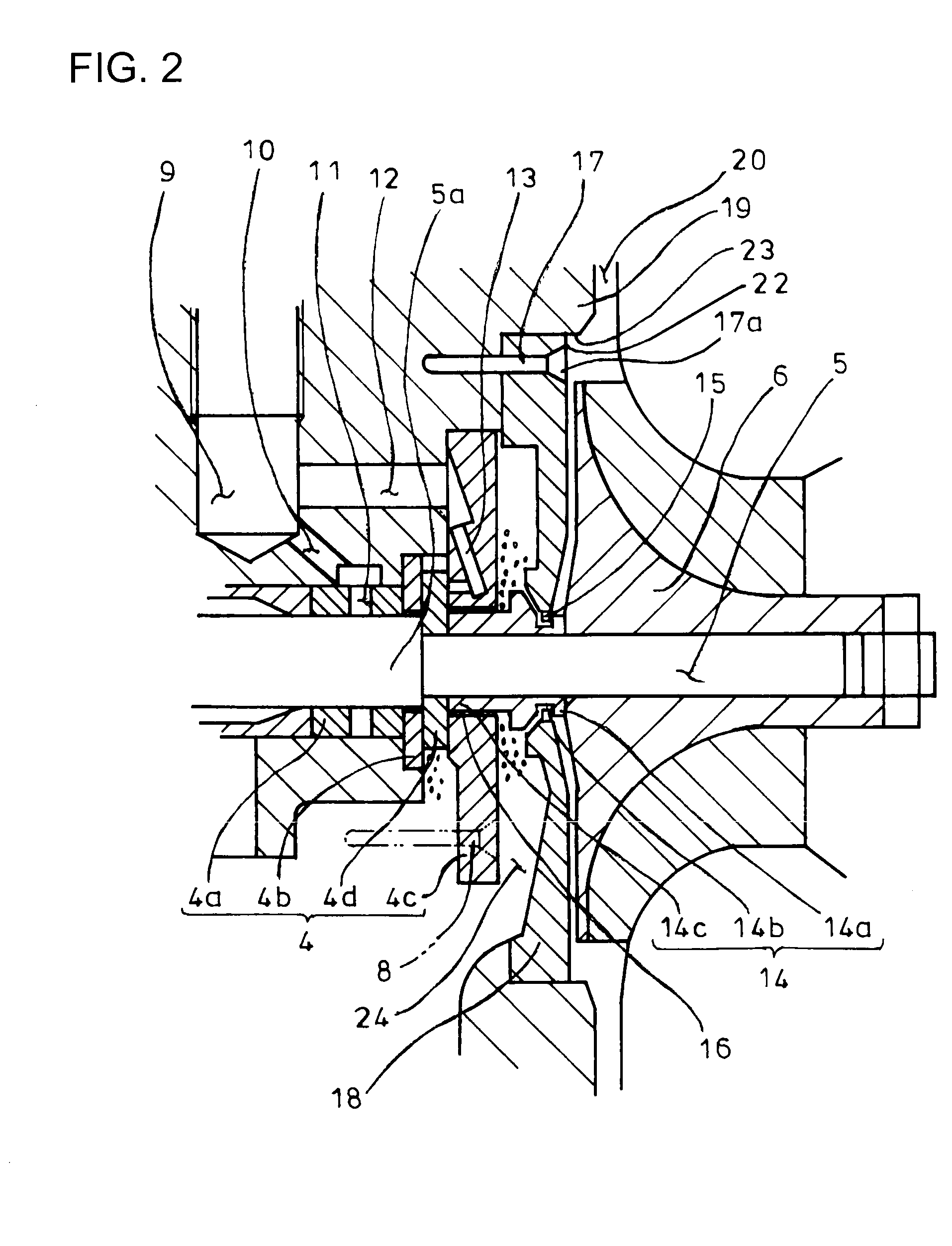
Moreover, when the seal plate 18 is assembled, the flow passage 20 of the diffuser 19 to which air is supercharged from the impeller 6 may be flawed for example by assembling tools; the flaws formed may similarly cause turbulence of the air to lower the supercharging efficiency.
Furthermore, thread machining and the like of the bearing housing 3 may increase machining cost and increased number of parts such as bolt 17 used for assembling of the seal plate 18 may increase production cost.
However, because of the turbine shaft 5 and oil thrower 14 being rotated at high velocity, the lubricant may be accumulated as mist around the bracket 4c, running down to the seal ring 15 and disadvantageously leaking via the ring 15 to the impeller 6.

Method used


Image

  • Turbocharger
  • Turbocharger
  • Turbocharger

Examples


Embodiment Construction

[0047]An embodiment of the invention will be described in conjunction with the attached drawings.

[0048]FIGS. 3-10 show the embodiment of the invention in which parts similar to those in FIGS. 1 and 2 are represented by the same reference numerals. The turbocharger according to the embodiment of the invention is constructed as mentioned below so as to overcome the problems in discharge of lubricant from the conventional bearing portion 4.

[0049]A bearing portion 31 as shown in FIGS. 3 and 4 which supports a turbine shaft 5 within a bearing housing 3 comprises a floating bush 32 which has unitary construction and supports the turbine shaft 5 at two portions. The floating bush 32 is supplied with lubricant from a supply opening 33 formed in the bearing housing 3 via a flow passage 34 extending from the opening 33 so that oil films are formed between the bush 32 and the housing 3 and between the bush 32 and the shaft 5 for support of rotation of the shaft 5. In this regard, for formation...


PUM


Abstract

In a turbocharger with an oil thrower 36 arranged between a bearing portion 31 for support of a turbine shaft 5 in a bearing housing 3 and an impeller 6 in front thereof, a seal plate 44 facing a front portion outer periphery of the oil thrower 36 for prevention of oil from leaking from the bearing portion 31 to the impeller 6 and being integral with the bearing housing 3 to be positioned at a back of the impeller 6, an oil-thrower facing part 39 formed in the bearing housing 3 to face a rear portion outer periphery of said oil thrower to provide an oil sump 40, the seal plate 44 is in the form of press-fit plate 47, a diameter of the press-fit plate 47 being smaller than an outer diameter of the impeller 6 and being at least equal to a minimum working bore diameter for machining of an outer periphery 42 of the oil-thrower facing part 39 or machining of oil discharge openings 41 provided in the oil-thrower facing part 39.

Description

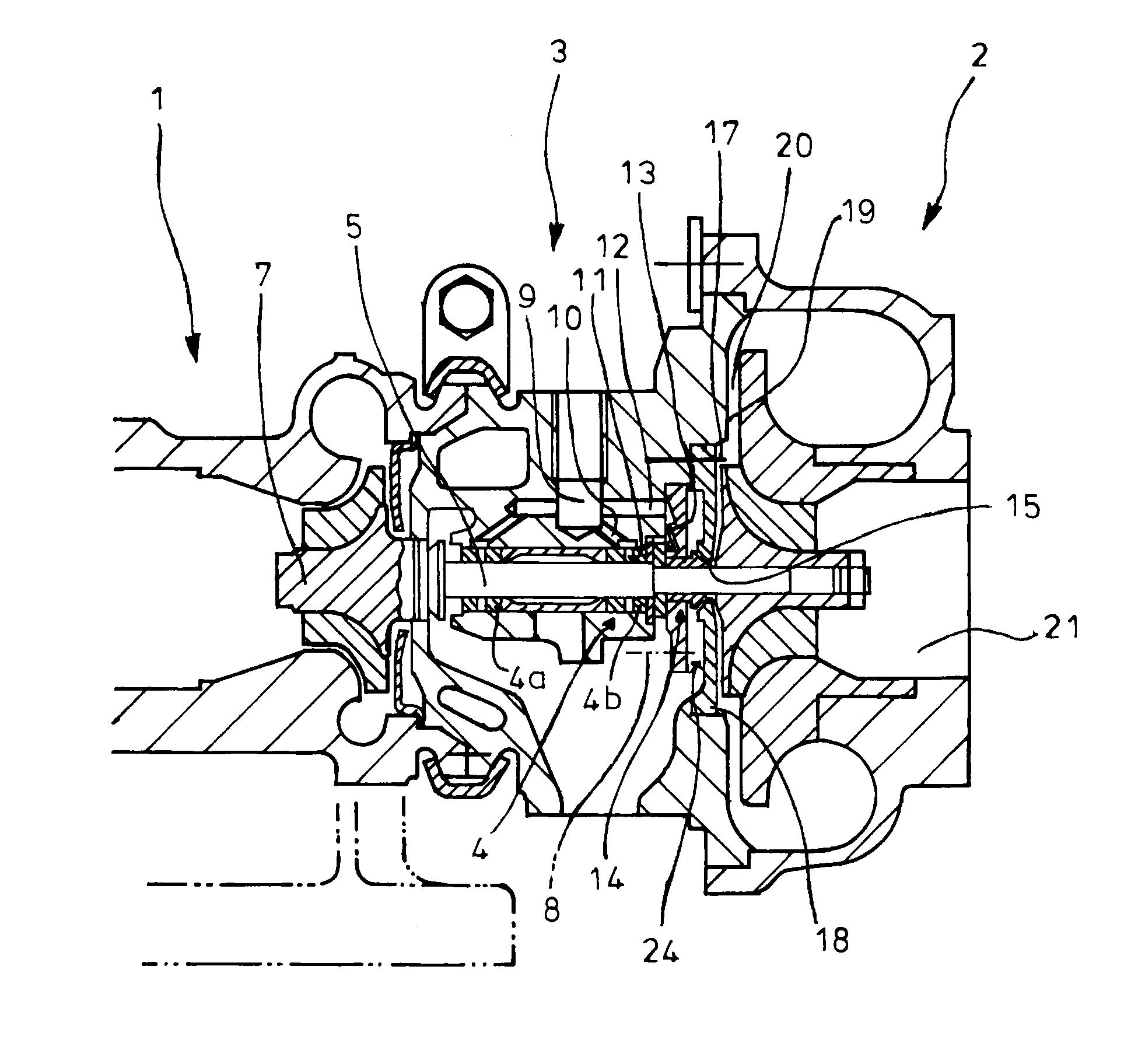
TECHNICAL FIELD[0001]The present invention relates to a turbocharger which prevents lubricant from a bearing portion from leaking to an impeller.BACKGROUND ART[0002]Generally, as shown in FIGS. 1 and 2, a turbocharger has a bearing housing 3 integrally arranged between turbine and compressor housings 1 and 2, a turbine shaft 5 being rotatably supported by the bearing housing 3 via a bearing portion 4. The turbine shaft 5 is provided on its one (front) side with an impeller 6 surrounded by the compressor housing 2 and on its other (rear) side with a turbine rotor 7 surrounded by the turbine housing 1.[0003]The bearing portion 4 in the bearing housing 3 is composed of a thrust bearing comprising floating bushes 4a arranged as rotary bearings on the turbine shaft 5 and spaced apart from each other axially of the shaft 5, an inner plate 4b which restrict axial movement of the floating bush 4a, an outer thrust bracket 4c fixed in the bearing housing 3 via a bolt 8 and a thrust collar 4d ...

Claims


Application Information

Patent Timeline
IPC IPC(8): F04D29/08
CPCF01D25/186F05D2260/37F05D2220/40F05D2240/70
Inventor MATSUYAMA, YOSHIMITSU
Owner IHI CORP
Learn More