Unilateral fixator

a fixator and lateral technology, applied in the field of orthopaedic medicine, can solve the problems of multiple and potentially endless configurations, the device joints must be loosened, and the device as a whole is grossly manipulated,

a fixator and lateral technology, applied in the field of orthopaedic medicine, can solve the problems of multiple and potentially endless configurations, the device joints must be loosened, and the device as a whole is grossly manipulated,

US20070282338A1Active Publication Date: 2007-12-06AMDT HLDG INC

Image

  • Unilateral fixator
  • Unilateral fixator
  • Unilateral fixator

Examples


Embodiment Construction

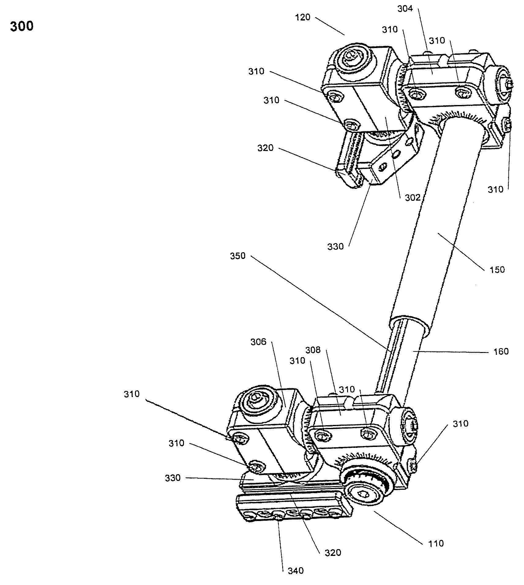
[0069] The following description is merely exemplary in nature and is not intended to limit the present disclosure, application, or uses. Exemplary embodiments of the present teachings provide a unilateral external fixator device that allows for gross manipulation and fine adjustment of deformities in six degrees of freedom, allowing for a large mechanical advantage and adjustments of the fixator through a deformity correction process without disengaging the device from the patient.

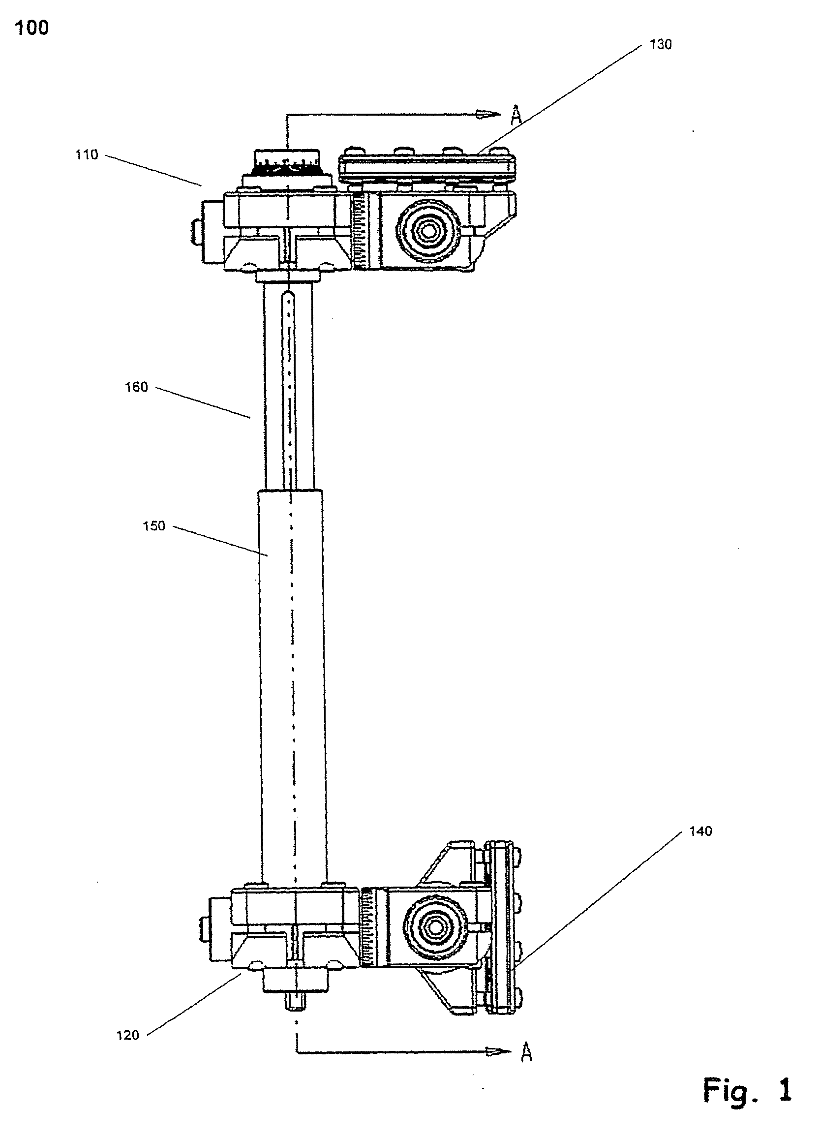
[0070]FIG. 1 provides an image of a unilateral fixator 100 in accordance with an exemplary embodiment of the present teachings. Referring to FIG. 1, the fixator 100 comprises two compound movable joints 110, 120. Attached to each compound movable joint 110, 120 is a pin clamp 130, 140. The pin clamp can accept a variety of pins (not shown), which can be attached to bone fragments undergoing a deformity correction procedure. The compound movable joint 110 is attached to an extension strut 160. The compoun...


PUM


Abstract

A unilateral fixator for adjustment of a first bone portion relative to a second bone portion. The fixator includes a telescopically adjustable strut having first and second ends and a strut axis, and first and second compound joints. The first compound joint is coupled to the first end of the strut and to a first bone clamp, and includes a first gear mechanism controlling linear and rotational motion of the first bone clamp relative to first and second axes while the first bone clamp is engaged with the first bone portion. The first and second axes are generally orthogonal to one another and to the strut axis. The second compound joint is coupled to the second end of the strut and to a second bone clamp and includes a second gear mechanism controlling linear and rotational adjustment of the second bone clamp. The first compound movable joints can rotate about the strut axis.

Description

CROSS-REFERENCE TO RELATED APPLICATIONS [0001] This application is a continuation of U.S. patent application Ser. No. 10 / 644,769 filed on Sep. 17, 2003, which claims priority from U.S. Provisional Patent Application No. 60 / 411,291 filed Sep. 17, 2002, and U.S. Provisional Patent Application No. 60 / 426,439, filed Nov. 14, 2002. The disclosures of the above applications are incorporated herein by reference.INTRODUCTION [0002] In orthopedic medicine, physicians often need to correct certain skeletal injuries or deformities with external fixator devices. These deformities can either be an acute or chronic condition that may be corrected over a short or long period of time. These devices use pins or wires attached to the separate bone segments and an external structural frame to align, or fix, the bone segments in a way to aid in repairing the injury or correcting the deformity. When the device is engaged with a patient, the device applies forces to maintain the bone fragments in a confi...

Claims


Application Information

Patent Timeline
06 Dec 2007
Publication
US20070282338A1
IPC
A61B17/60; A61B17/56; A61B17/64; A61B17/66; A61B19/00
CPC
A61B17/6458; A61B17/66; A61B2019/5238; A61B2017/564; A61B19/50; A61B2090/376; A61B34/10
Inventors
MULLANEY, MICHAEL W.