Sensor, a system and a method for measuring forces and/or moments

a technology of sensors and moments, applied in the direction of force measurement, instruments, optical elements, etc., can solve the problems of inability to use a plurality of measuring points for temperature measurement, inability to measure the wavelength of fiber bragg grating ex post, and inability to meet the measurement requirements of wavelength and other issues

Inactive Publication Date: 2014-07-15
DEUTSCHES ZENTRUM FUER LUFT & RAUMFAHRT EV
View PDF13 Cites 1 Cited by
  • Summary
  • Abstract
  • Description
  • Claims
  • Application Information

AI Technical Summary

Benefits of technology

[0013]Such a sensor is advantageous in that the volume of the sheath material enclosing the fiber core is substantially larger than that of the fiber core having the same length so that the quantity of fluorescent material is much larger compared to a single-mode fiber of the same length. The amount of light of the fluorescent radiation generated by the sensor element of the invention is thus mostly sufficient to reduce signal noise and to allow a very precise measurement. In such a sensor element, the excitation radiation used to generate the fluorescent radiation can be obtained by means of laser diodes whose radiation is emitted from multi-mode fibers. Compared to laser diodes coupled to single-mode fibers, such laser diodes have a clearly higher output power in the fiber, whereby the measuring signal is stronger. Moreover, laser diodes whose radiation is emitted from a multi-mode fiber are clearly more economic to procure than laser diodes coupled to single-mode fibers.
[0048]It may also be provided with respect to the present sensors, the present method and a present system using a plurality of fiber Bragg gratings that the fiber Bragg gratings have different grating periods so that, although the expansion is the same, the peak wavelengths of the light reflected from the fiber Bragg gratings differ from each other and can thus be discriminated. Thereby, it becomes possible to differentiate between the signals from the different fiber Bragg gratings and to evaluate them individually in a simple manner.

Problems solved by technology

The measured wavelength of the fiber Bragg grating is not suited for an ex post determination of which proportion results from temperature variation and which proportion results from variation by expansion.
It is another drawback of this invention that it supposes a uniform temperature across the entire sensor body.
If, for example, such a sensor is used on a minimally invasive surgical instrument, one cannot assume a defined temperature of the entire sensor since, for example, flushing solutions or contact with organs may lead to an inhomogeneous temperature distribution across the instrument.
On the other hand, using a plurality of measuring points for temperature measurement is often impractical or impossible for reasons of space; further, it is also possible that the entire sensor characteristic is changed by additional temperature sensors.
However, such sensors must have a certain length since the number of atoms excited to fluorescence is limited due to the very small diameter of the single-mode fiber core and therefore only very little fluorescent radiation is reflected.
The amount of light of the fluorescent radiation can be so small that the signal-to-noise ratio does not allow for a sufficiently accurate compensation.
Often, the marginal conditions do not allow for an elongation of the measuring site and thus for an enlarging of the region in which the fluorescent material is provided.
On the other hand, a heavier doping of the glass fiber material is often impossible as well, since the properties of the glass mixture could be modified by the doping and, in addition thereto, the doping atoms in some fluorescent doping materials influence each other strongly when the concentration is high, whereby the measurement could be compromised.

Method used


Image

  • Sensor, a system and a method for measuring forces and/or moments
  • Sensor, a system and a method for measuring forces and/or moments

Examples


Embodiment Construction

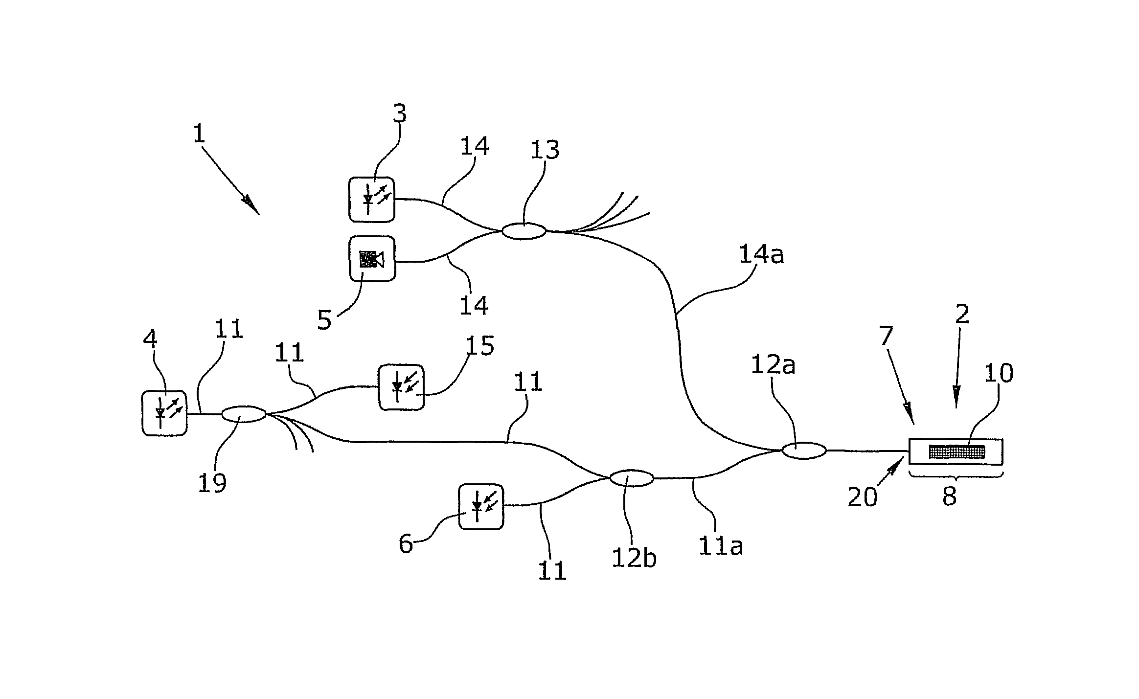
[0053]FIG. 1 is a schematic illustration of the present system 1 for measuring forces and / or moments on an object. The object is not illustrated in the Figure.

[0054]The system 1 of the present invention comprises at least one sensor 2, a first light source 3, a second light source 4, a first detector 5 and a second detector 6.

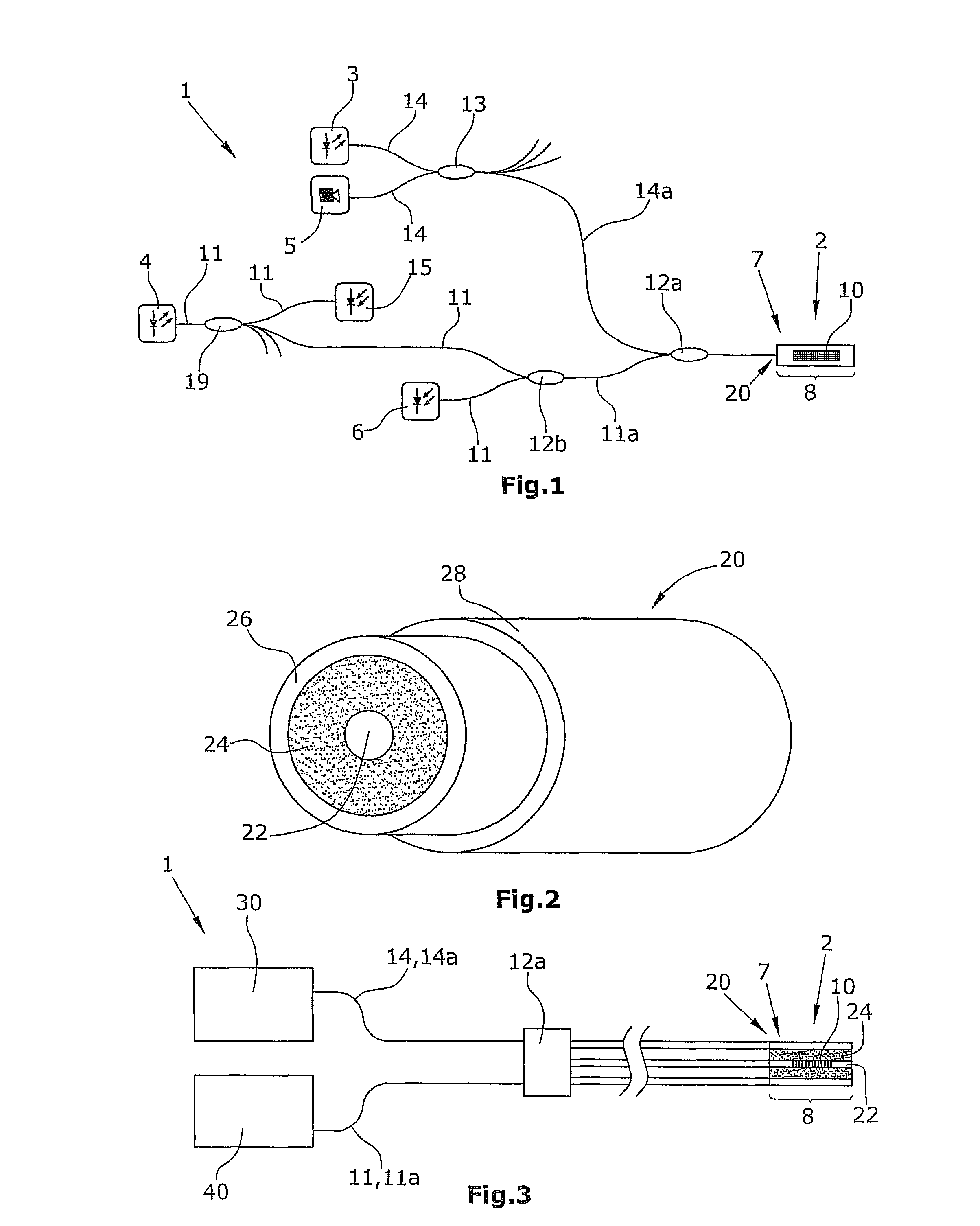
[0055]The sensor 2 is formed by an optical fiber 20 comprising a sensor region 8. A fiber Bragg grating 10 is arranged in this sensor region 8. In the sensor region 8, the optical fiber 20 is doped with a fluorescent material not illustrated in the Figure. The exact structure of the optical fiber is illustrated in FIG. 2.

[0056]The first light source 3 and the second light source 4 are connected to the sensor 2 via optical fibers 11, 11a, 14, 14a and coupler elements 12a, 12b. The first detector 5 and the second detector 6 are also connected to the sensor 2 through optical fibers 11, 11a, 14, 14a.

[0057]The first light source 3 preferably generates a broadband l...


PUM


Abstract

A sensor for measuring forces and / or moments on an object, including at least one sensor element for the detection of an expansion of the object in at least one spatial direction, from which expansion a force or a moment can be determined, wherein the sensor element including an optical fiber with a sensor region with a fiber Bragg grating is provided, and the fiber Bragg grating is adapted to be irradiated with light, preferably a broadband light, generating a reflected light having a peak wavelength. The optical fiber is formed by a fiber core and at least one sheath of light-guiding material surrounding the fiber core. The fiber Bragg grating is arranged in the fiber core. The material of the sheath is doped with a fluorescent material and the fluorescent material may be irradiated with an excitation radiation to generate a fluorescent radiation having at least one main emission wavelength.

Description

RELATED APPLICATIONS[0001]This application claims the benefit of priority under 35 U.S.C. §119 to German Patent Application No. 10 2010 052 614.2 filed on Nov. 29, 2010, the disclosure of which is incorporated by reference herein its entirety.BACKGROUND OF THE INVENTION[0002]1. Field of the Invention[0003]The present invention refers to a sensor for measuring forces and / or moments, to a method for measuring forces and / or moments, as well as to a system for measuring forces and / or moments on an object, for example on a device for minimally invasive surgery.[0004]2. Description of the Prior Art[0005]It is known, for example, to use fiber Bragg gratings (FBG) with sensors for measuring forces and / or moments. Here, the degree of expansion of the fiber Bragg grating, and thus the degree of expansion of the object on which the sensor is arranged, is determined from the light reflected by the fiber Bragg grating. The degree of expansion can then be used to determine a force and / or a moment...

Claims


Application Information

Patent Timeline
Patent Type & Authority Patents(United States)
IPC IPC(8): G02B6/00
CPCG01B11/18G01B1/00G01D5/35303G01D5/35316G01L1/246G01L1/26
Inventor HASLINGER, ROBERT
Owner DEUTSCHES ZENTRUM FUER LUFT & RAUMFAHRT EV
Why Eureka
Try Eureka