Ballast for a discharge lamp

a discharge lamp and ballast technology, applied in the direction of electric variable regulation, process and machine control, instruments, etc., can solve the problems of inability to accept ballast, low switching frequency, and failure to turn off the switching elemen

Inactive Publication Date: 2001-09-11
MATSUSHITA ELECTRIC WORKS LTD
View PDF8 Cites 81 Cited by
  • Summary
  • Abstract
  • Description
  • Claims
  • Application Information

AI Technical Summary

Benefits of technology

Preferably, the controller gives the maximum OFF-end limit which varies in accordance with the output condition of the voltage converter so that the OFF-period can terminate at an optimum timing for keeping the suitable switching frequency even in the absence of the secondary current decreasing to zero. For this purpose, the controller monitors an output power of the voltage converter as indicative of the output condition and provides the command value based upon the output power. The controller causes the forced maximum OFF-end limit to vary in accordance with the command value in a direction of shortening the OFF-period as the command value demands to flow an increased current through the switching element. Thus, it is possible to increase the output power without accompanying the lowering the switching frequency. This is particularly suitable for rapidly increasing lamp luminosity at a so-called cold start condition where the lamp voltage is low.
Preferably, the controller may include a comparator which compares an output voltage of the voltage converter with an allowable maximum voltage and issues a limit signal when the output voltage exceeds the allowable maximum voltage. In response to the limit signal, the controller operates to prolong the subsequent OFF-period until the output voltage goes below the allowable maximum voltage, thereby preventing the voltage converter from providing an excess output voltage at the time of starting the lamp.
Further, the controller may be configured to give the command value having an upper limit which defines a maximum current allowed to flow through the switching element. Thus, it is possible to avoid an excess current flowing through the switching element.
The controller may include a delay circuit which delays an increase of the command value when the voltage converter starts operating, thereby enabling a soft-starting of the ballast for reducing stresses applied to the switching element and other components of the voltage converter.
Further, the controller may include a restrictor which reduces the upper limit of the command value to a low level for a predetermined starting period from the start of operating the ballast and restores the upper limit to a high level thereafter, thereby reducing stresses applied to the switching element and other components of the voltage converter at the start of operating the ballast.
Also, the controller may include an output voltage monitor which monitors an output voltage of the voltage converter so as to reduce the upper limit to a lower level as the output voltage becomes greater. Thus, it is possible to limit the ON-period at the start of operating the ballast, i.e., at a no-load condition, for restricting the switching current to a moderate level, thereby reducing stress applied to the switching element as well as other components of the voltage converter.

Problems solved by technology

However, this may pose a problem that the switching element should fail to turn off when the current to the inductance does not increase to the predetermined high level, as seen in a case where the DC source voltage gives a high impedance.
Further, if the switching element is turned off after a long period, i.e., the ON-period becomes considerably long, the switching frequency would goes too low into an audible range, which is not acceptable for the ballast.

Method used


Image

  • Ballast for a discharge lamp
  • Ballast for a discharge lamp
  • Ballast for a discharge lamp

Examples


Embodiment Construction

This application is based on application No. 11-147193 filed in Japan, the content of which is incorporated hereinto by reference.

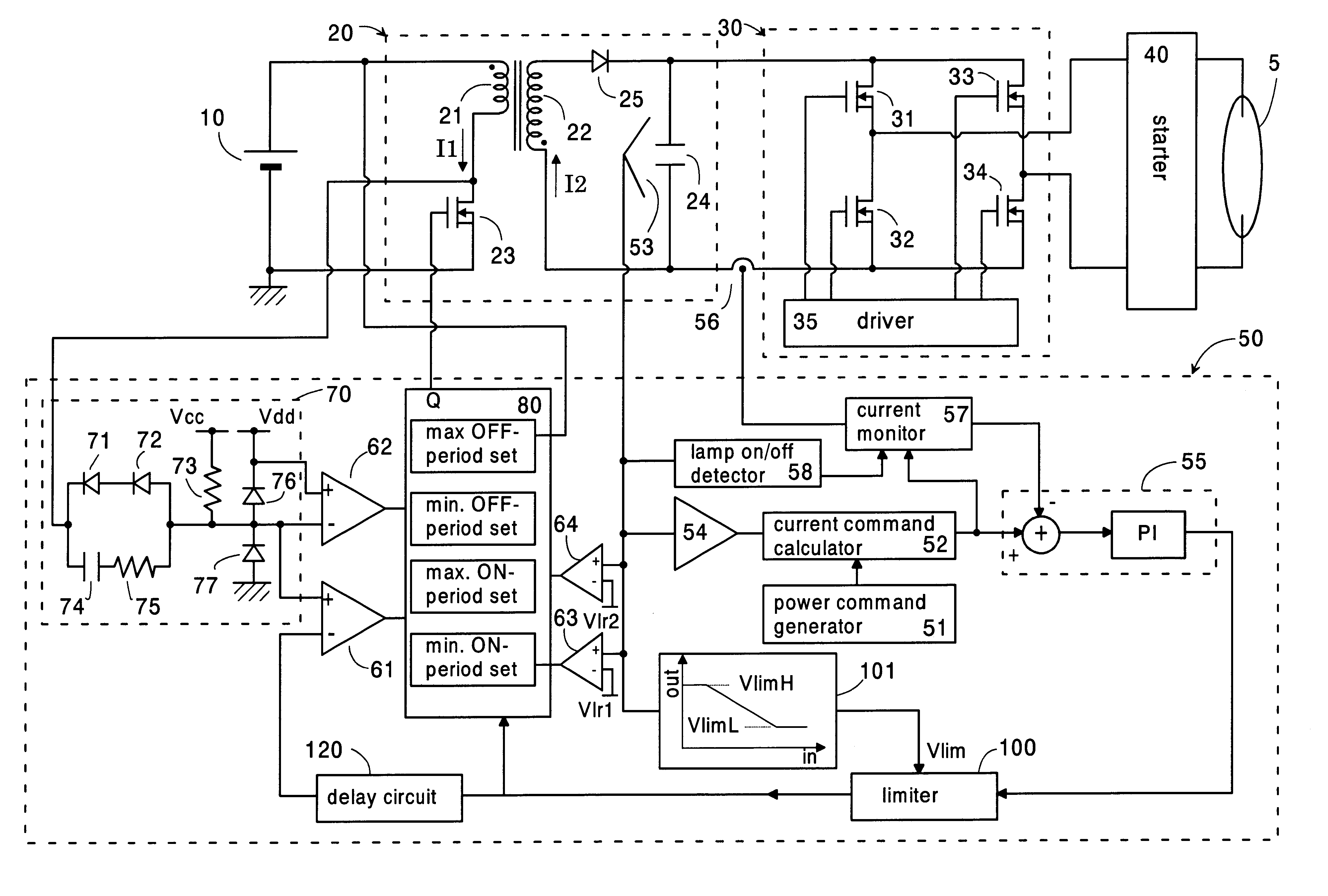
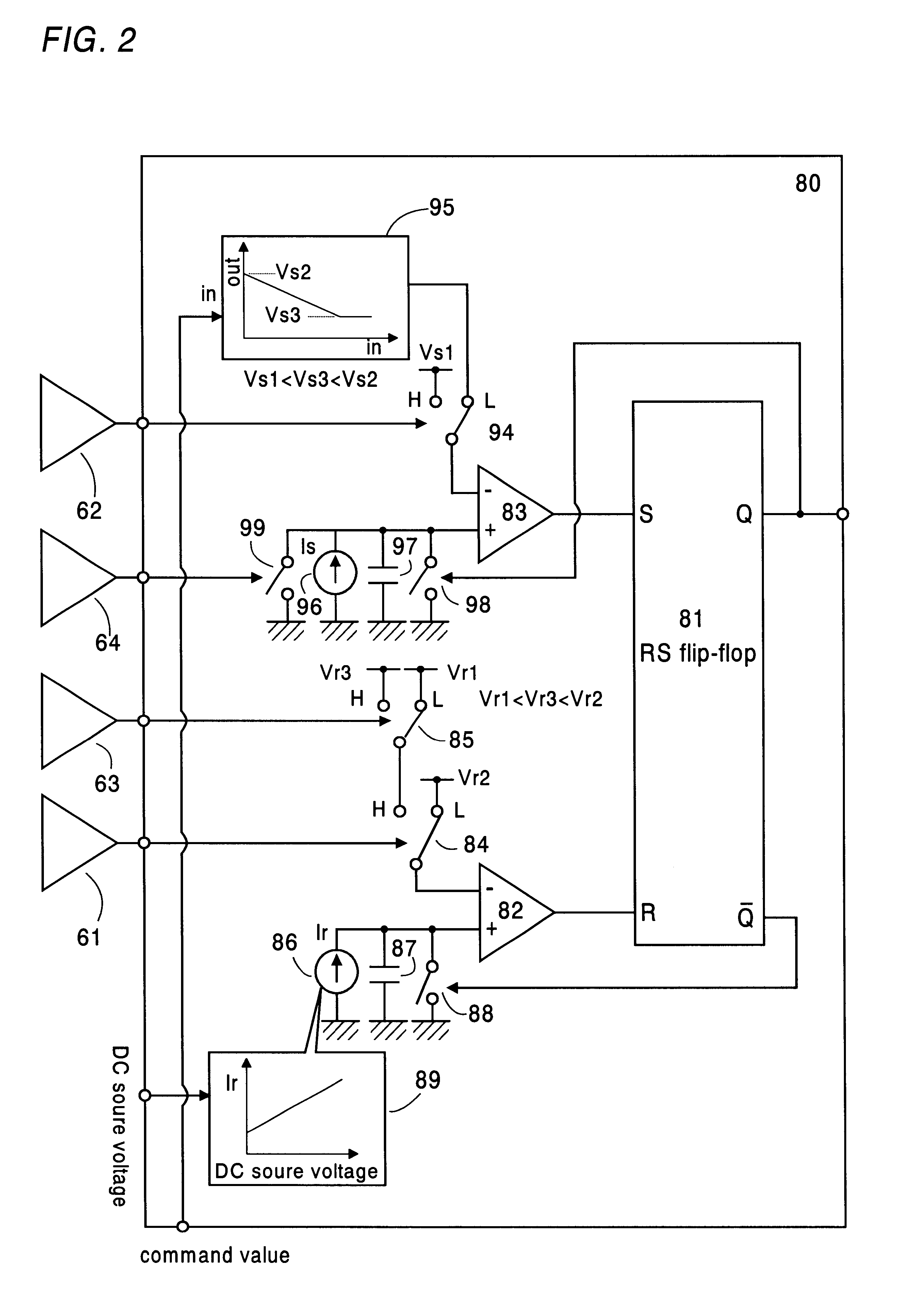
Referring now to FIG. 1, there is shown a ballast for a discharge lamp in accordance with a first embodiment of the present invention. The ballast comprises a voltage converter 20 providing a smoothed DC voltage from a DC source voltage supplied from a battery 10, an inverter 30 receiving the DC voltage and providing an AC voltage which is applied through a starter 40 to operate the discharge lamp 5, for example, a high intensity discharge lamp utilized as a headlamp of an automobile.

The converter 20 is configured as a fly-back converter comprising a transformer with a primary winding 21 and a secondary winding 22, and a switching element or transistor 23 connected in series with the primary winding across the battery 10. The transistor 23 is driven by a controller 50 to turn on and off for repetitively interrupt a primary current I1 flowing through the p...


PUM


Abstract

A ballast includes a voltage converter providing a DC power from a DC source voltage. The converter includes a switching element and an energy storing element having an inductance. The switching element is controlled to operate for repetitively switching the DC source voltage in order to store energy into the energy storing element. A power converter is included in the ballast to receive the energy and convert it into an operating power for driving the discharge lamp. A controller provides a command value and turns on and off the switching element for variable periods, respectively in accordance with the command value for generating a necessary power to the lamp. The controller gives a variable OFF-period and a variable ON-period to the switching element. The controller gives a minimum OFF-end limit and a forced maximum OFF-end limit for terminating the OFF-period, and also gives a minimum ON-end limit and a forced maximum ON-end limit for terminating the variable ON-period. The minimum OFF-end limit is defined at a timing when a secondary current flowing from the inductance decreases to zero, while the minimum ON-end limit is defined at a timing when a primary current flowing through the switching element reaches the command value. The controller terminates the OFF-period at the minimum OFF-end limit or at the forced maximum OFF-end limit, whichever comes earlier, and terminates the ON-period at the minimum ON-end limit or at said forced maximum ON-end limit, whichever comes earlier.

Description

1. Field of the InventionThe present invention relates to a ballast for a discharge lamp, and more particularly, an electronic ballast provided with a voltage converter which provides a DC power from a DC source voltage for operating the discharge lamp.2. Description of the Prior ArtJapanese Patent No. 10-511220 discloses a ballast for a discharge lamp which includes a voltage converter providing a DC power from a DC source voltage for operating the discharge lamp, and a controller for controlling DC power in a feedback manner based upon an output condition of the voltage converter. The voltage converter includes an inductance and a switching element which is controlled by the controller to turn on and off in order to accumulate an energy in the inductance and allow the energy to release from the inductance for applying the resulting power to operate the discharge lamp. The controller is basically configured to give a varying OFF-period of the switching element for effecting a mode ...

Claims


Application Information

Patent Timeline
Patent Type & Authority Patents(United States)
IPC IPC(8): H05B41/28H05B41/39H05B41/288H05B41/392H05B41/282
CPCH05B41/2886H05B41/392Y02B20/202Y02B20/00
Inventor NAKAMURA, TOSHIAKIKONISHI, HIROFUMISHIOMI, TSUTOMU
Owner MATSUSHITA ELECTRIC WORKS LTD
Why Eureka
Try Eureka