Light emitting apparatus

a technology support member, which is applied in the direction of light and heating apparatus, display means, point-like light sources, etc., can solve the problems of reducing the emission output power of light emitting apparatus, deterioration of metal parts provided on the support member, and discoloration, so as to prevent the deterioration of metal parts

Active Publication Date: 2008-11-04
NICHIA CORP
View PDF4 Cites 87 Cited by
  • Summary
  • Abstract
  • Description
  • Claims
  • Application Information

AI Technical Summary

Benefits of technology

[0008]Accordingly, an object of the present invention is to provide a light emitting apparatus which has a high output power and does not experience a decrease in the emission output power.
[0016]In the light emitting apparatus of the present invention having such a constitution as described above, since the light emitting elements are placed in the recess so that the distance between the metallic member and a side face having the largest area becomes larger, light emerging from the side face is prevented from concentrating in a part of the metallic member, thereby preventing the metallic member from deteriorating.

Problems solved by technology

However, with the trend toward higher output power of the light emitting element, the metallic member provided on the support member may experience deterioration including discoloration, due to the light and heat generated by the light emitting element.
Silver, in particular, has high reflectivity to the light from the light emitting element and is therefore preferably used in the reflector wall of the support member, but is likely to deteriorate due to the light and heat generated by the light emitting element.
As a result, a part of the light generated by the light emitting element is absorbed by the deteriorated silver, thus resulting in decreasing emission output power of the light emitting apparatus.
This may cause the metallic member provided on the side wall surface of the recess to be greatly affected by the light emitted by the light emitting element.

Method used


Image

  • Light emitting apparatus
  • Light emitting apparatus
  • Light emitting apparatus

Examples


example

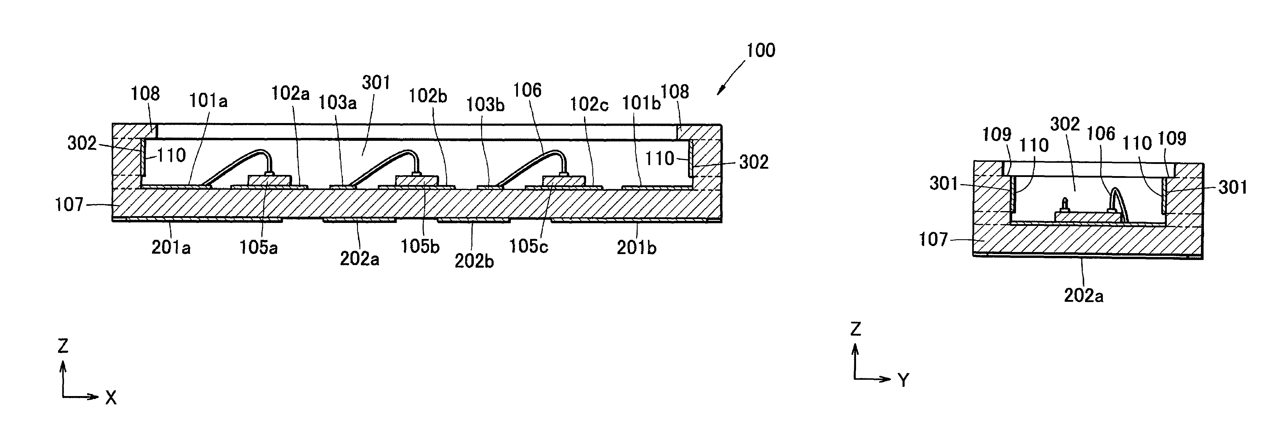
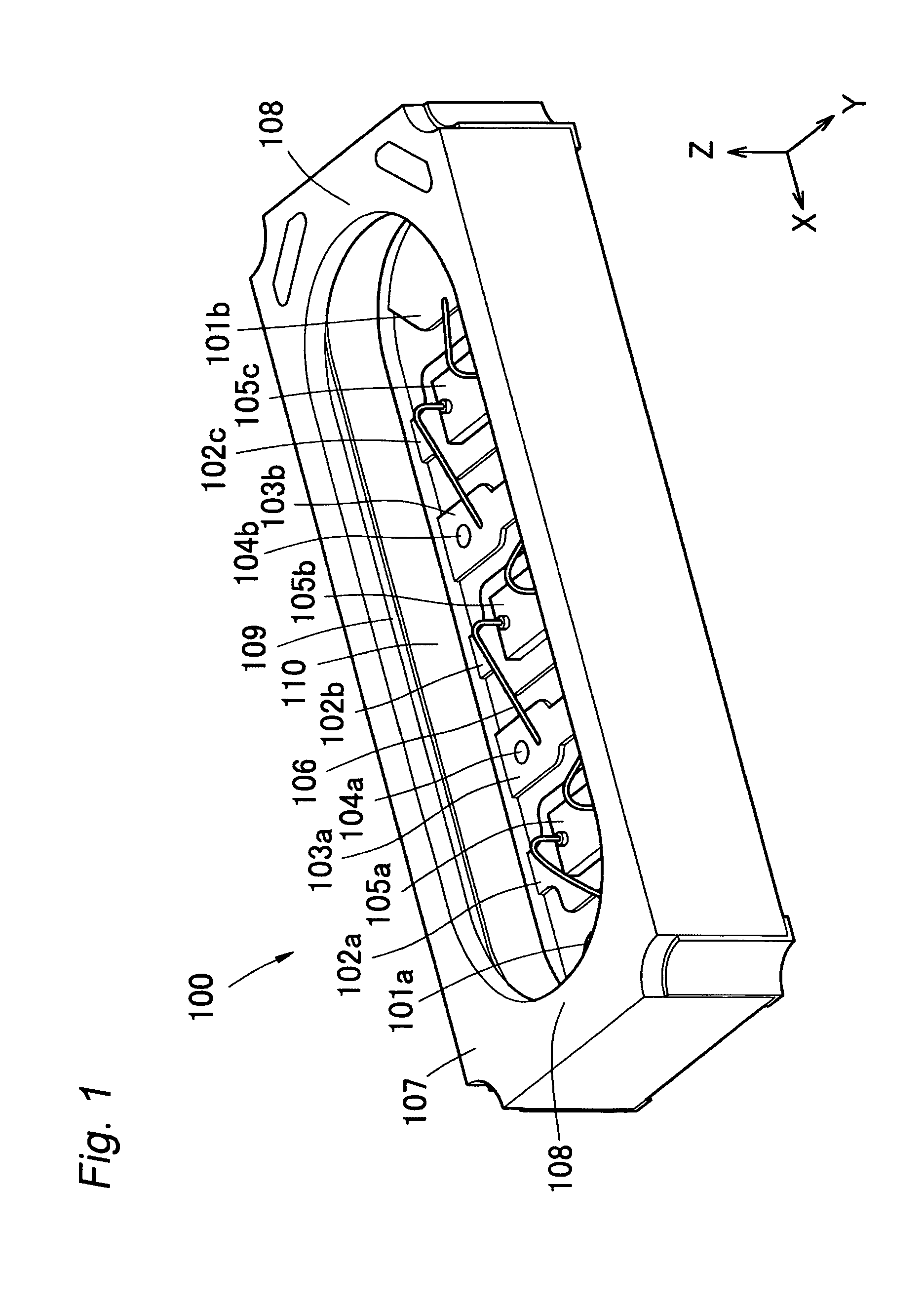
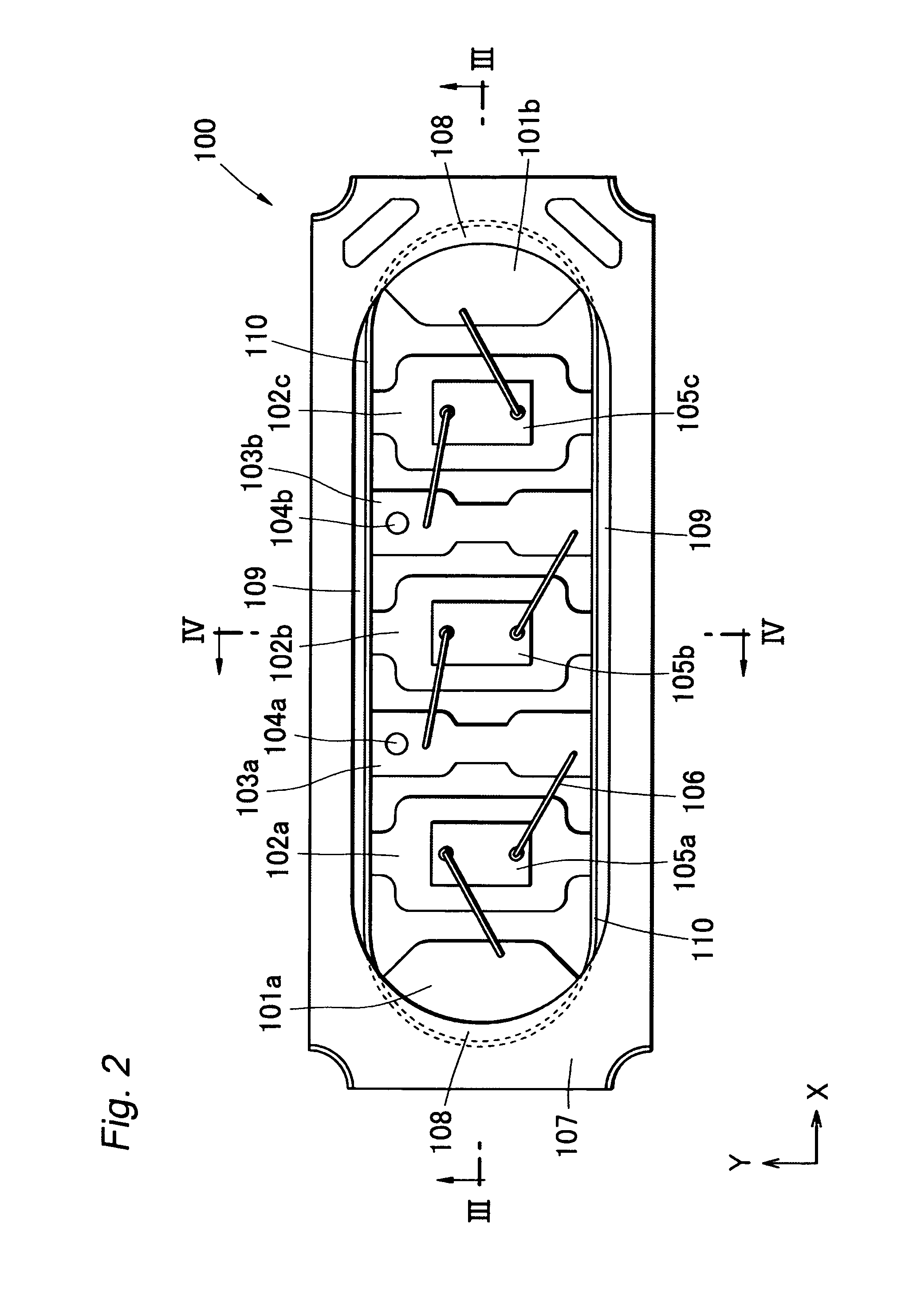
[0078]FIG. 1 is a perspective view of the light emitting apparatus according to one Example of the present invention. FIG. 2 is a top view of the light emitting apparatus according to this example viewed from the opening of the recess. FIG. 3 is a rear view of the light emitting apparatus according to this example viewed from the side opposite to the side where the recess is formed. FIG. 4 is a sectional view along X axis direction of the light emitting apparatus of this example. FIG. 5 is a sectional view along Y axis direction of the light emitting apparatus of this example. In FIG. 4 and FIG. 5, Z axis is defined as the direction from the bottom surface of the recess of the support member toward the opening.

[0079]The light emitting apparatus of this example comprises LED chips 105a, 105b, 105c having rectangular contour and the support member having the recess wherein the LED chips are mounted at the bottom surface thereof. The support member has the substrate made of ceramics, t...


PUM


Abstract

A light emitting apparatus comprises a light emitting element which has one of main surfaces thereof being used as a light emitting surface and a plurality of side faces having different areas, and a support member which has a recess with metallic members provided on the side wall surfaces thereof for reflecting the light emitted by the light emitting element. The light emitting element is placed in the recess so that the distance between the metallic member and a side face having the largest surface area among the plurality of side faces of the light emitting element is larger than the distance between the metallic member and the other side face.

Description

BACKGROUND OF THE INVENTION[0001]1. Field of the Invention[0002]The present invention relates to a light emitting apparatus which can be used as illumination apparatus, display, light source for backlight of liquid crystal display, etc. and, more particularly, to a light emitting apparatus having high reliability.[0003]2. Description of the Related Art[0004]Some of light sources used for illumination apparatus, backlight of liquid crystal display, etc. employ semiconductor light emitting element. The semiconductor light emitting element consumes less electric power than the conventional light sources, lasts longer and allow it to make the light emitting apparatus smaller, and is therefore preferably used. There is a demand for a light emitting apparatus which emits light with higher output power by using the semiconductor light emitting element.[0005]In a light emitting apparatus of the prior art disclosed in Japanese Unexamined Patent Publication No. 2004-207672, for example, a sup...

Claims


Application Information

Patent Timeline
Patent Type & Authority Patents(United States)
IPC IPC(8): F21V1/00H01L33/56H01L33/60H01L33/62
CPCH01L33/486H01L33/60H01L25/0753H01L33/20H01L33/62H01L2224/48091H01L2224/48465Y10S362/80H01L2924/00014H01L2224/48247H01L2224/48227H01L2924/00H01L2924/01322
Inventor AOKI, YUKOTAKAHASHI, HIROKI
Owner NICHIA CORP
Why Eureka
Try Eureka