Image sensing apparatus, image sensing system, and image sensing method

a technology image sensing system, which is applied in the field of image sensing apparatus, can solve the problems of increasing costs or power consumption, requiring a sufficient exposure time, and difficult to use the technique in high-speed control, and achieves the effect of high frame ra

Inactive Publication Date: 2007-09-27
COLUMBIA PEAK VENTURES LLC
View PDF5 Cites 55 Cited by
  • Summary
  • Abstract
  • Description
  • Claims
  • Application Information

AI Technical Summary

Benefits of technology

[0014]An advantage of an aspect of the invention is that it provides an image sensing apparatus capable of acquiring, with a single image sensing element, a high frame-rate image having a relatively high frame rate enabling to detect a target object having a relatively high moving speed and extract the shape of the target object as well as a normal image having a relative low frame rate providing an image quality that can be perceived by a human, and generating a control data for use in controlling a control object requiring a relatively high control speed (response speed or detection speed) on the basis of the high frame-rate image.

Problems solved by technology

However, since the background image sensed by the on-vehicle camera cannot be specified and is likely to change with time, it is difficult to use the technique in the high-speed control.
In addition, video images recorded by a drive recorder before and after an accident need to have sufficient visibility and thus require a sufficient exposure time.
That is, since the photographic object is sensed at a frame rate (exposure time) providing a sufficient exposure time, it may be difficult for the on-vehicle camera to acquire a high frame-rate image for use in a high-speed control Thus, in order to implement the high-speed control in the known technology, there is a need to use two cameras, one for the high-speed control and the other for the visibility.
Since the use of two cameras may cause a problem of increasing costs or power consumption, it is desirable to implement with a single camera.
However, when an image is acquired at a high speed in the single camera implementation for a stable control, the acquired image may have a poor S / N characteristic due to an insufficient exposure time and it is thus impossible to acquire an image having a quality for use in other purposes.
Moreover, since the photoelectric conversion elements (pixels) constituting the photoelectric conversion unit may generate fixed pattern noise resulting from their irregular characteristics, much noise components are likely to be mixed into the pixel data composed of the charge read out in the non-destructive readout mode.
However, when the edge information is extracted from a digital image, the digital image is not continuous and thus, strictly speaking, the differential operation cannot be performed.

Method used


Image

  • Image sensing apparatus, image sensing system, and image sensing method
  • Image sensing apparatus, image sensing system, and image sensing method
  • Image sensing apparatus, image sensing system, and image sensing method

Examples


Embodiment Construction

[0089]Hereinafter, embodiments of an image sensing apparatus related to the invention will be described with reference to the accompanying drawings. FIGS. 1 to 13 are diagrams for explaining the embodiments of the image sensing apparatus 1 related to the invention.

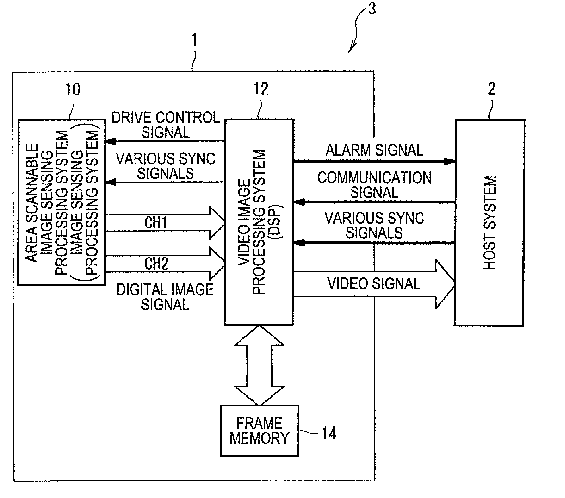
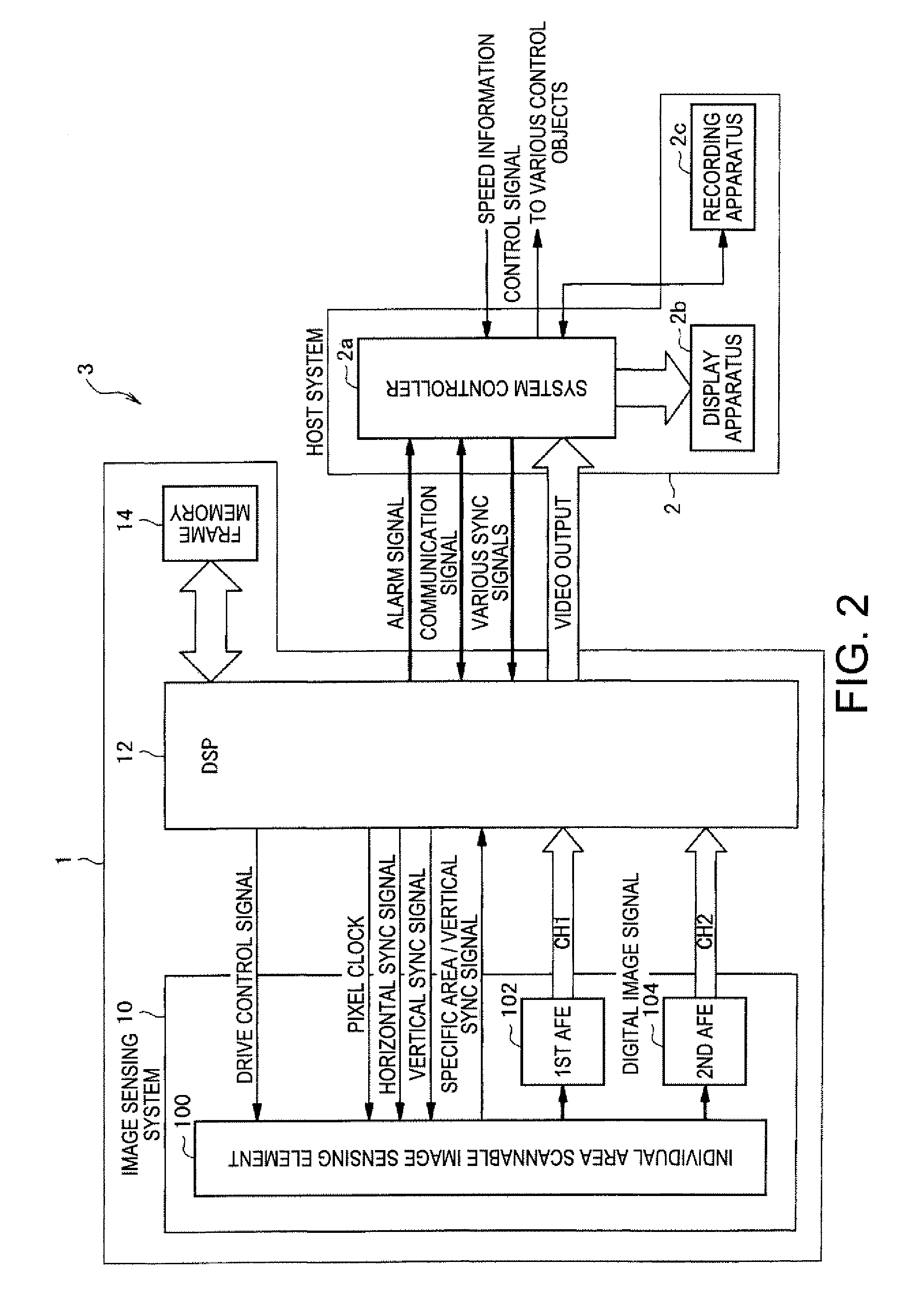
[0090]First, a schematic arrangement of an image sensing system 3 employing the image sensing apparatus 1 related to the invention will be described with reference to FIG. 1. Here, FIG. 1 is a schematic block diagram showing an arrangement of the image sensing system 3 related to the invention. The image sensing system 3 related to the invention includes the image sensing apparatus 1 mounted on a mobile object and aims to monitor a target photographic object (target object) in a forward area of the mobile object.

[0091]As shown in FIG. 1, the image sensing system 3 is configured to include an image sensing apparatus 1 which senses, in one frame period (one exposure period), an image obtained by exposing an entire exposure a...


PUM


Abstract

There is provided an image sensing apparatus. The image sensing apparatus includes a photoelectric conversion unit constituted by a plurality of photoelectric conversion elements converting exposed light into charge and accumulating the charge therein, and an exposure time control function for controlling an exposure time of the photoelectric conversion elements, the apparatus including: a first readout unit that reads out charge from pixels composed of the photoelectric conversion elements of the photoelectric conversion unit, the charge being accumulated in the pixels as a result of exposure for a predetermined exposure time; a second readout unit that reads out charge from pixels of a specific area in a predetermined area of the photoelectric conversion unit over a plurality of times, in a period when the first readout unit is reading out charge from the pixels of the predetermined area of the photoelectric conversion unit; an image data generation unit that generates an image data on the basis of a first pixel data composed of the charge read out by the first readout unit; and a predetermined data generation unit that generates a predetermined data on the basis of a second pixel data composed of the charge read over the plurality of times by the second readout unit.

Description

BACKGROUND[0001]1. Technical Field[0002]The present invention relates to an image sensing apparatus capable of reading out charge from a photoelectric conversion element using both destructive and non-destructive readout modes.[0003]2. Related Art[0004]Recently, a monitoring camera mounted on a mobile object is attracting attention. For example, there is known a monitoring camera, known as an on-vehicle camera, which is mounted on a vehicle. The on-vehicle camera may be used in detecting a centerline or guardrail on a road or rail, an inter-vehicle distance to a preceding or following vehicle, and an abrupt change in contrast at the entrance to a tunnel. The recognition or detection result is output to a control unit of a predetermined control object (for example, brakes, steering, or alarm systems), and the control unit controls the control object on the basis of the detection result and takes measures against unforeseen changes in situation or accidents that may be caused by a per...

Claims


Application Information

Patent Timeline
Patent Type & Authority Applications(United States)
IPC IPC(8): H04N5/335G06T1/00H04N5/235H04N5/341H04N5/345H04N5/353H04N5/374
CPCH04N3/1562H04N25/443H04N25/533
Inventor KURANE, HARUHISA
Owner COLUMBIA PEAK VENTURES LLC
Why Eureka
Try Eureka