Plasma display panel
a technology of display panel and plasma, which is applied in the direction of gas-filled discharge tubes, electric discharge tubes, gas exhaustion means, etc., can solve the problems of irregular discharge, non-uniform local luminance, undetected impurities between discharge cells, etc., and achieve the effect of stabilizing discharge characteristics
- Summary
- Abstract
- Description
- Claims
- Application Information
AI Technical Summary
Benefits of technology
Problems solved by technology
Method used
Image

Examples
first embodiment
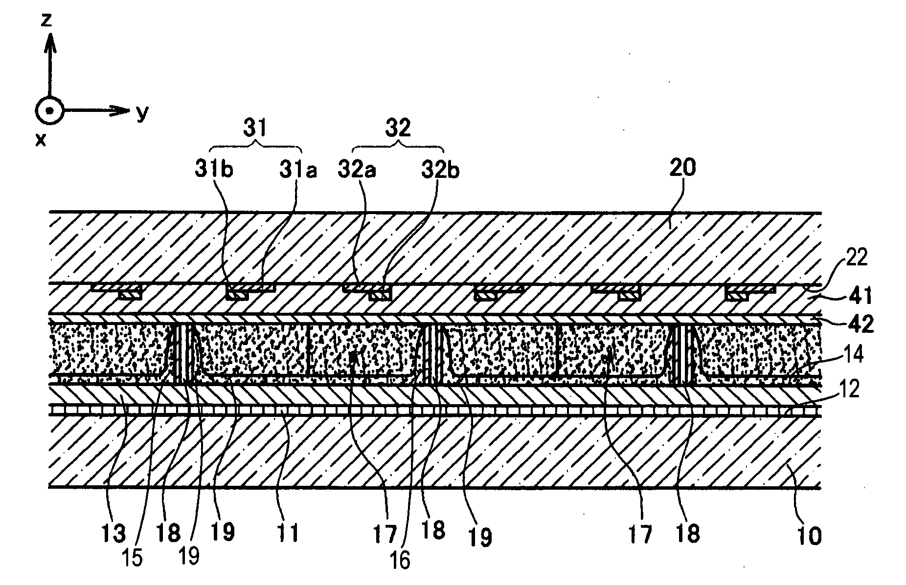
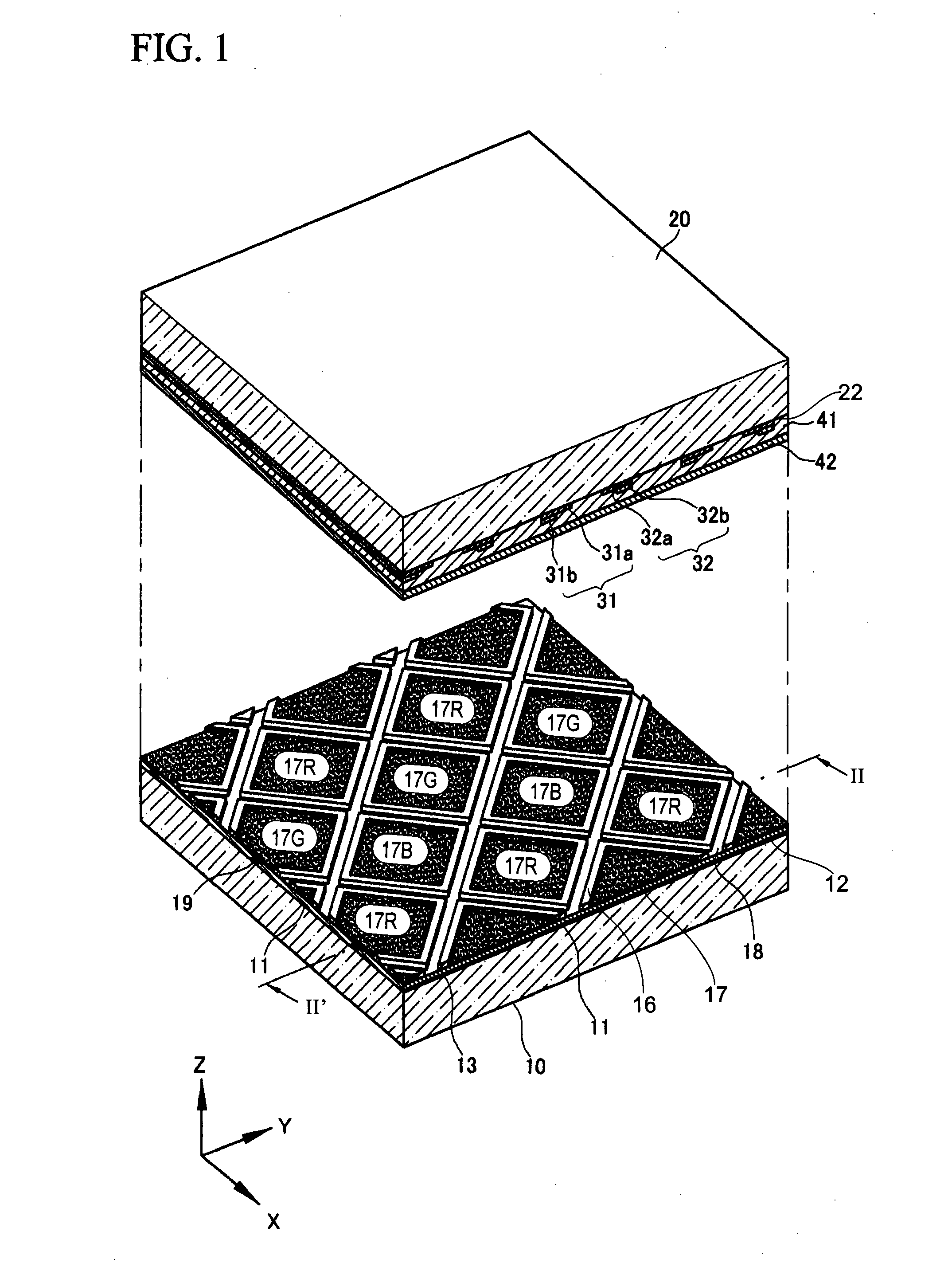
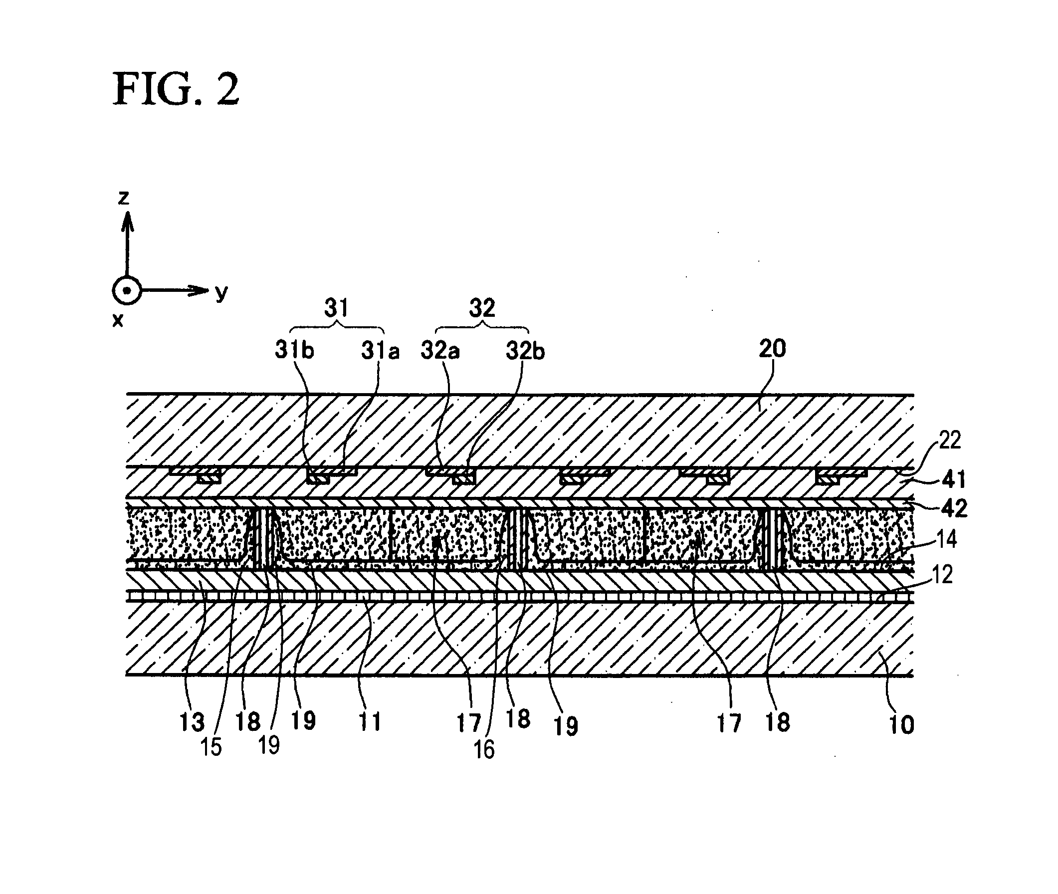
[0040]FIG. 1 is a perspective view schematically illustrating a plasma display panel according to the present invention by exploding the plasma display panel. FIG. 2 is a cross sectional view taken along line II-II′ of FIG. 1.
[0041]Referring to FIGS. 1 and 2, the plasma display panel according to the first embodiment of the principles of the present invention is constructed with a first substrate 10 (hereinafter, referred to as “rear substrate”) and a second substrate 20 (hereinafter, referred to as “front substrate”) which are sealed to face each other with a certain gap, and a barrier rib 16 which is disposed between first and second substrates 10 and 20.
[0042]Barrier rib 16 is formed with a certain height to define a plurality of discharge cells 17 between rear and front substrates 10 and 20.
[0043]Discharge cells 17 are filled with a discharge gas (for example, a gas mixture including neon (Ne) and xenon (Xe)) so as to generate vacuum ultraviolet rays through gas discharge. Each ...
second embodiment
[0074]FIG. 4 is a top plan view illustrating an arrangement of barrier ribs and discharge cells according to the principles of the present invention.
[0075]Since the arrangement structure of the barrier ribs and the discharge cells according to the second embodiment of the present invention is similar to that of FIG. 3 according to the first embodiment of the present invention, the arrangement structure according to the second embodiment will be described in comparison with the arrangement structure according to the first embodiment.
[0076]Barrier ribs 16 of the plasma display panel according to the first embodiment of the present invention define separate discharge cells 17 in x-axis and y-axis directions. Exhaust paths 18 are formed in third and fourth directions D3 and D4 so as to improve exhaust performance.
[0077]On the other hand, barrier ribs 116 of the plasma display panel according to the second embodiment of the present invention form exhaust paths 118 by defining discharge c...
third embodiment
[0081]FIG. 5 is a top plan view illustrating an arrangement of barrier ribs and discharge cells according to the principles of the present invention.
[0082]Since an arrangement structure of barrier ribs and discharge cells of the plasma display panel according to the third embodiment of the present invention is similar to that of FIG. 3 according to the first embodiment of the present invention, the arrangement structure according to the third embodiment will be described in comparison with the arrangement structure according to the first embodiment.
[0083]Barrier ribs 16 of the plasma display panel according to the first embodiment of the present invention define separate discharge cells 17 in x-axis and y-axis directions. Exhaust paths 18 are formed in third and fourth directions D3 and D4 so as to improve exhaust performance.
[0084]On the other hand, barrier ribs 216 of the plasma display panel according to the third embodiment of the present invention form exhaust paths 218 by defi...
PUM
 Abstract
Description
Claims
Application Information