Liquid discharging head, liquid-discharging device and producing method for liquid-discharging head

A liquid discharge head, liquid technology, applied in the manufacture of such a liquid discharge head, a liquid discharge and recording device, a liquid discharge device, and the field of the manufacture of such a discharge head, can solve problems such as pinholes and cracks

Inactive Publication Date: 2007-07-11
CANON KK
View PDF6 Cites 0 Cited by
  • Summary
  • Abstract
  • Description
  • Claims
  • Application Information

AI Technical Summary

Problems solved by technology

In addition, the deposited film is formed on the substrate and the pattern of the deposited film forming the movable member is constructed, therefore, pinholes and cracks may occur at the edge of the side portion of the movable member

Method used


Image

  • Liquid discharging head, liquid-discharging device and producing method for liquid-discharging head
  • Liquid discharging head, liquid-discharging device and producing method for liquid-discharging head
  • Liquid discharging head, liquid-discharging device and producing method for liquid-discharging head

Examples


no. 1 example

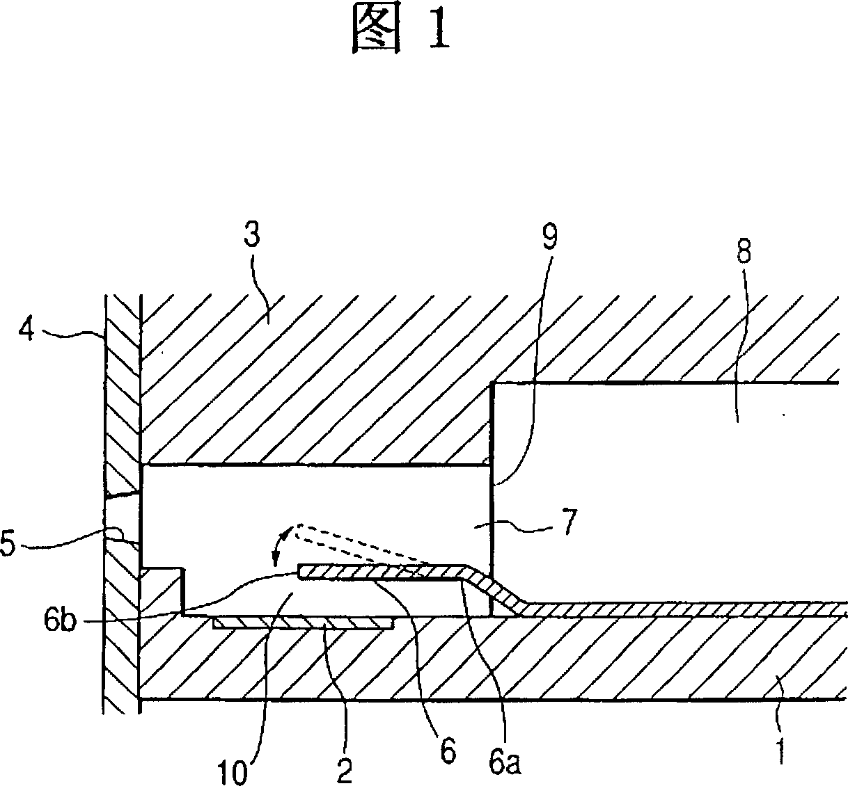
[0065] FIG. 1 is a sectional view along a liquid flow direction for explaining the basic structure of a liquid discharge head according to a first embodiment of the present invention. The liquid discharge head of the present invention has as shown in Figure 1: a device substrate 1, on which a plurality of (only one is shown in Figure 1) heating elements 2 installed in parallel as discharge energy generating means, which generate thermal energy Make the liquid generate bubbles and apply heat energy to the liquid; the top plate 3 attached to the top of the device substrate 1 ;

[0066] The device substrate 1 is an element with heat insulation and heat storage, and a silicon dioxide film or a silicon nitride film is formed on a substrate made of silicon and other materials, and a resistance layer and a heating element 2 are formed on it. The wires form a pattern. The heating element 2 is heated by applying a voltage from a wire to the resistance layer and supplying a current to ...

no. 2 example

[0103] 9A, 9B are cross-sectional views for explaining the structure of a liquid discharge head manufactured by a method of manufacturing a liquid discharge head according to a second embodiment of the present invention. The liquid discharge head according to this embodiment is mainly different from the liquid discharge head of the first embodiment in that the width of the electrode layer on the device substrate is smaller than that of the movable member. Differences from the first embodiment are mainly described below. In Figs. 9A and 9B, the same reference numerals are used for the same parts as those of the first embodiment.

[0104] In the liquid discharge head according to the present embodiment, as shown in FIGS. 9A and 9B , the width W6 on the movable member 6 in the direction perpendicular to the liquid flow direction of the liquid flow path 7 and parallel to the surface of the device substrate 1 greater than the width W5 in the direction perpendicular to the liquid f...


PUM


Abstract

A method of manufacturing a liquid discharge head having a liquid flow path, a discharge energy generating device in the liquid flow path, a discharge port communicating with the liquid flow path, and a movable member facing the discharge energy generating device. The movable member is formed by a photolithographic technique, and a right-angled part and an acute-angled part of an edge of the movable member are removed so as to make a surface of the edge of the movable member curved. The curved surface of the movable member serves to reduce concentration of the stress on the movable member that occurs due to displacement of the movable member resulting from pressure of a bubble generated to discharge ink. Removal of the right-angled and acute-angled parts may be performed by soaking the movable member in an etching solution after formation of the movable member.

Description

technical field [0001] The present invention relates to a liquid discharge head and a liquid discharge device which are used in printers and image printers as output terminals of copiers, facsimile machines, word processors, host computers, etc., and to manufacture of such a liquid discharge head Methods. In particular, the present invention relates to a liquid discharge head having a device substrate on which an electrothermal device is formed to generate thermal energy for discharging liquid, a liquid discharge and recording device on which a liquid discharge head is mounted, and manufacturing This method of liquid draining the head. In other words, the present invention relates to a liquid discharge head that performs recording by discharging a recording liquid such as recording ink from a discharge port as flying droplets to attach the liquid to a recording medium, and a method of manufacturing such a discharge head. Background technique [0002] Well known is an ink j...

Claims


Application Information

Patent Timeline
Patent Type & Authority Patents(China)
IPC IPC(8): B41J2/14B41J2/16
CPCY10S29/016B41J2/1604B41J2/1628B41J2/1634B41J2/14048B41J2/1642B41J2/1631B41J2/1629B41J2/1645Y10T29/49083Y10T29/49401
Inventor 杉山裕之石永博之三隈义范种谷阳一
Owner CANON KK
Why Eureka
Try Eureka