
PDP provided with green phosphor layer having a height difference in relation to red/blue phosphor layers and corresponding barrier ribs

a technology of green phosphor and height difference, applied in the field of pdp, to achieve the effect of stable discharge characteristics

Inactive Publication Date: 2008-06-03
SAMSUNG SDI CO LTD
View PDF10 Cites 0 Cited by
  • Summary
  • Abstract
  • Description
  • Claims
  • Application Information

AI Technical Summary

Benefits of technology

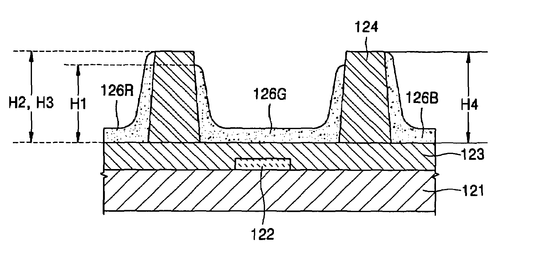
[0017]The present invention provides a PDP that may have more stable discharge characteristics by forming a green phosphor layer lower than a barrier rib.

Problems solved by technology

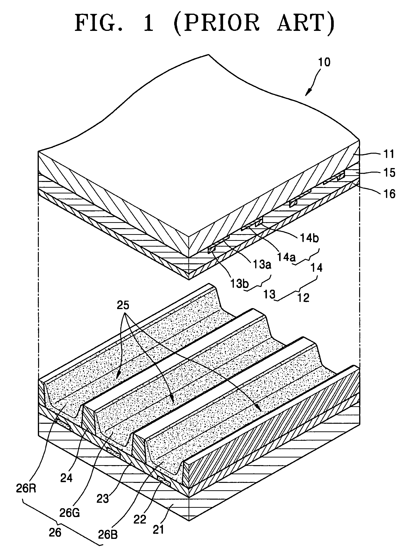
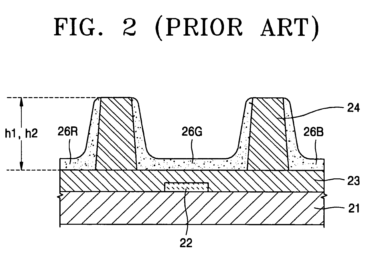
However, changing the green phosphor material's polarity may change the address discharge characteristics, which may affect the following sustain discharge.

Method used


Image

  • PDP provided with green phosphor layer having a height difference in relation to red/blue phosphor layers and corresponding barrier ribs
  • PDP provided with green phosphor layer having a height difference in relation to red/blue phosphor layers and corresponding barrier ribs
  • PDP provided with green phosphor layer having a height difference in relation to red/blue phosphor layers and corresponding barrier ribs

Examples


Embodiment Construction

[0028]FIG. 3 is a perspective view showing a PDP according to an exemplary embodiment of the present invention.

[0029]Referring to FIG. 3, the PDP 100 may include an upper substrate 111 and a lower substrate 121 facing the upper substrate 111.

[0030]The upper substrate 111 may be formed of a transparent material, such as, for example, glass so that light may transmit through it. A plurality of sustain electrode pairs 112 may be arranged on a surface of the upper substrate 111 facing the lower substrate 121. The sustain electrode pairs 112 may include a common electrode 113 and a scan electrode 114.

[0031]The common electrode 113 and the scan electrode 114 may include transparent electrodes 113a and 114a and bus electrodes 113b and 114b, respectively. The bus electrodes 113b and 114b may be connected to edges of the transparent electrodes 113a and 114a. Here, the transparent electrodes 113a and 114a are formed as strips, and the bus electrodes 113b and 114b are narrower than the transpa...


PUM


Abstract

A PDP includes a barrier rib formed between an upper substrate and a lower substrate to define discharge regions, and a phosphor layer including red, green, and blue phosphor layers corresponding to the discharge regions. A height of the green phosphor layer is lower than a height of the barrier rib.

Description

CROSS REFERENCE TO RELATED APPLICATION[0001]This application claims priority to and the benefit of Korean Patent Application No. 10-2004-0038183, filed on May 28, 2004, which is hereby incorporated by reference for all purposes as if fully set forth herein.BACKGROUND OF THE INVENTION[0002]1. Field of the Invention[0003]The present invention relates to a plasma display panel (PDP), and more particularly, a PDP having an improved structure that may provide a high level of discharge stability.[0004]2. Discussion of the Background[0005]Generally, in a PDP, applying a predetermined voltage to electrodes having a gas filled between them generates a glow discharge, which generates ultraviolet rays that excite a phosphor layer to emit light, thereby displaying an image.[0006]PDPs can be classified as direct current (DC) PDPs, alternating current (AC) PDPs, or hybrid PDPs according to their driving methods. A PDP can also be classified as a two-electrode type or a three-electrode type accord...

Claims


Application Information

Patent Timeline
Patent Type & Authority Patents(United States)
IPC IPC(8): H01J17/49G09G3/20G09G3/288G09G3/291G09G3/292G09G3/293G09G3/298H01J11/12H01J11/22H01J11/24H01J11/26H01J11/34H01J11/42
CPCH01J11/12H01J11/36H01J11/42G09G3/291G09G3/292
Inventor KANG, TAE-KYOUNGKWON, JAE-IK
Owner SAMSUNG SDI CO LTD
Learn More