Manufacturing method and apparatus for plastic membranes

A manufacturing method and a manufacturing device technology, which are applied in the field of plastic film manufacturing and devices, can solve problems such as uneven stretching at the end of film products, unstable width changes, and sparks, so as to avoid spark discharge failures, excellent quality, Effect of Stable Discharge Characteristics

Active Publication Date: 2013-01-09
UNITIKA LTD
View PDF1 Cites 0 Cited by
  • Summary
  • Abstract
  • Description
  • Claims
  • Application Information

AI Technical Summary

Problems solved by technology

[0013] The more troublesome problem is that in order not to directly spark discharge to CR, it is best for the front end of the insulating sleeve to be located 5-10mm inward from the left and right ends of the film-like melt along the width direction of the melt, but if it is covered by an insulating sleeve The electrode covered by the tube itself is at an abnormally high temperature, and the exposed part of the electrode at the front end of the insulating sleeve tends to generate sparks obliquely
In order to avoid this, it is necessary to place the insulating sleeve further inside in the width direction of the molten body. As a result, since the end of the film-like molten body cannot be tightly formed with the CR, unstable width fluctuations occur.
This is a major problem of uneven stretching at the end of the film product in the subsequent biaxial stretching process

Method used


Image

  • Manufacturing method and apparatus for plastic membranes
  • Manufacturing method and apparatus for plastic membranes

Examples


Embodiment 1

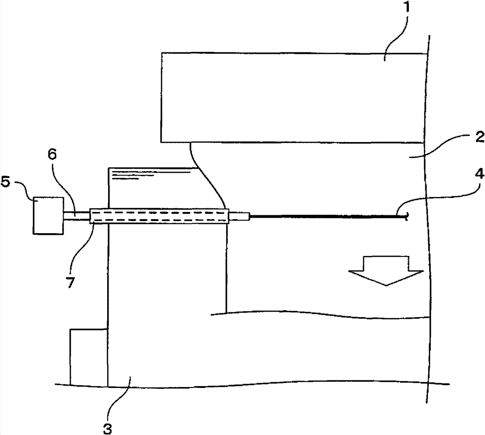
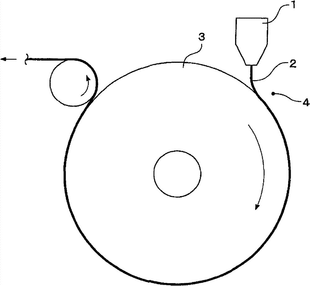
[0051] Molten polyethylene terephthalate is extruded in a film form from a T-shaped die head, and a cooling roll with a surface temperature of 20°C is rotated at a speed of 60m / min, and is cooled and formed into a film with a width of 1100mm and a thickness of 195μm by electrostatic bonding. Unoriented film.

[0052] At this time, a tungsten wire with a diameter of 0.1 mm was erected at a distance of 1450 mm between the supports near the junction of the film-like melt and the cooling roll, and a tungsten wire of 10 mm inward from the end of the film-like melt in the width direction from the support to the melt was placed. Position, set the secondary electrode made of stainless steel tube on the electrode cover. The magnification of the cross-sectional area by the sub-electrode is 6.2 times, and the conduction resistance is about 1 / 3. Also cover the two ends of the electrode with ceramic sleeves for insulation, and make the front end of the sleeve enter a position about 3 mm i...

Embodiment 2

[0059] Under the same conditions as in Example 1 except for the following, it was cooled and formed into a polyethylene terephthalate film.

[0060] That is, instead of the lead wire of Example 1, a stainless steel blade with a width of 3 mm and a thickness of 0.02 mm was erected at a distance between the supports of 1450 mm in the vicinity of the junction of the film-like melt and the cooling roll, and the film was compared in the width direction from the support to the melt. As far as the end of the molten body is 10 mm inside, the sub-electrodes are placed between the U-shaped fittings. The magnification ratio of the cross-sectional area by the sub-electrode is 6.2 times, and the conduction resistance is about 1 / 4. Both ends of the electrode were also covered with a ceramic sleeve so that the front end of the sleeve entered a position about 3 mm inward from the end of the film-like melt in the width direction of the melt. A heating current was flowed into the electrode, an...


PUM


Abstract

The invention relates to manufacturing method and apparatus for plastic membranes. A membrane shaped fuse member is closely attached to the surface of the rotary cooling roller by an electrostatic adhesion process. Therefore, electrodes can be heated to and maintained at high temperature, attachment of low molecular weight substances to electrodes can be prevented, long-term discharge stability and discharge easiness can be obtained, spark discharge failure generated at the electrode terminals can be avoided. As a result, plastic membrane with excellent quality can be produced stably in industry. Melt resin can be extruded in membrane shape from the mold head (1), and the membrane shaped fuse member (2) is closely attached to the surface of the rotary cooling roller (3) by an electrostatic adhesion process. Electric current directly flows to the electrode (4) close to the rotary cooling roller (3) and arranged along the width direction of the membrane shaped fuse member (2) for the heating of the heater. The electrode (4) causes the resistors having relatively lower position than the inner side of the end portion of the fuse body (2) to be lowered than other members, wherein the resistors are provided on the width direction from the supporting portions (5) on both ends.

Description

technical field [0001] The present invention relates to a method and apparatus for producing a plastic film, and in particular, to a film capable of maintaining operational stability when an electrostatic adhesion method is used in the cooling and solidification process after extruding a molten resin from a die, and obtaining a film of excellent quality A method and apparatus for producing a plastic film. Background technique [0002] In the usual film-making process of plastic film using the T-die method, the following method is adopted: the resin in the molten state is extruded in the form of a film from the extruder through the T-die, and the extruded film-like melt is It is squeezed onto the surface of a rotationally driven cooling roll (hereinafter referred to as CR) called a casting roll, thereby cooling and solidifying. Further, the film formed by cooling is biaxially stretched along the vertical axis and the horizontal axis in the next stretching process, thereby fi...

Claims


Application Information

Patent Timeline
Patent Type & Authority Patents(China)
IPC IPC(8): B29C47/00B29C47/88B29C48/08B29C48/305
CPCB29C48/08B29C48/914B29C48/9165
Inventor 坪内健二
Owner UNITIKA LTD
Why Eureka
Try Eureka