

Antenna
- Summary
- Abstract
- Description
- Claims
- Application Information
AI Technical Summary
Benefits of technology
Problems solved by technology
Method used
Image

Examples
first embodiment
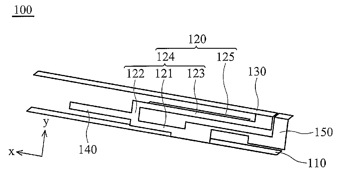
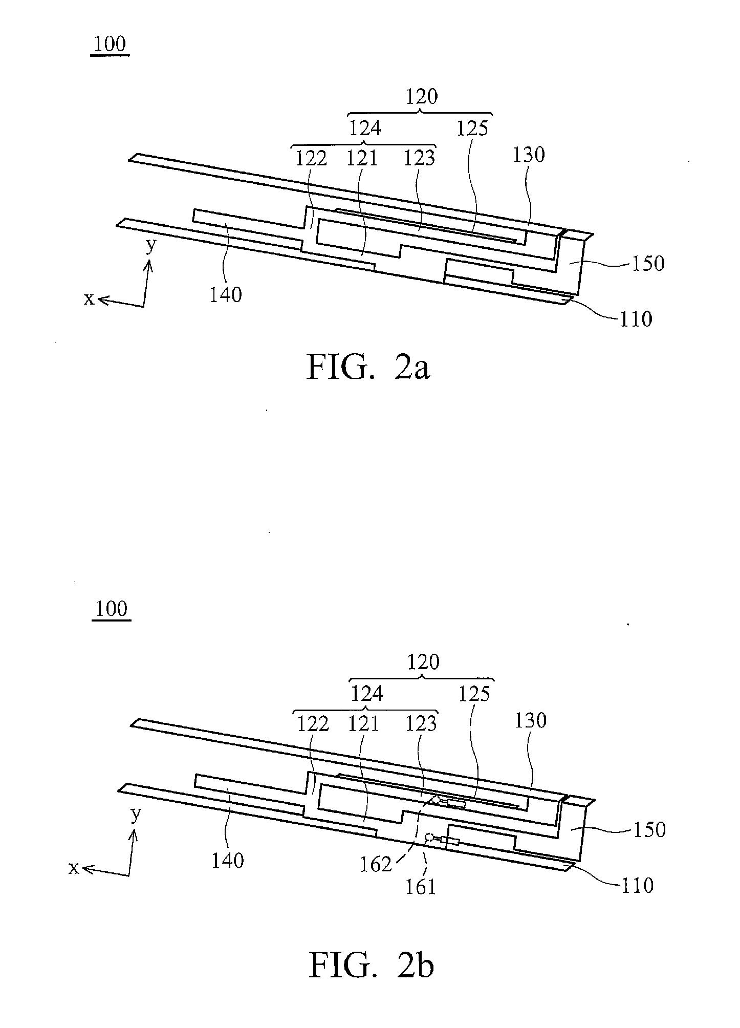
[0021]FIG. 2a shows an antenna 100 of the invention, comprising a ground element 110, a conductive element 120, a transmission element 130, a first matching element 140 and a second matching element 150, wherein the first matching element 140 and the second matching element 150 is capable of adjusting the matching effect of the antenna and allowing the antenna transmitting and receiving wireless signals with frequency between 1710-2179 MHz. The conductive element 120 is connected to the ground element 110. The transmission element 130 is connected to the conductive element 120. The conductive element 120 comprises a conductive portion 124 and a coupling portion 125. The conductive portion 124 connects the ground element 110 and the transmission element 130. The coupling portion 125 is connected to the conductive portion 124 corresponding to the transmission element 130.
[0022]The coupling portion 125 is located on a first plane, and the transmission element 130 is located on a second...
second embodiment
[0029]FIG. 3a shows an antenna 200 of the invention, from which the first matching element 140 and the second matching element 150 are eliminated. FIG. 3b shows the transmission of the antenna 200, which provides increased bandwidth nearing 900 MHz and 1800 MHz.
[0030]FIG. 4a shows an antenna 300 of a third embodiment of the invention. Relative to the first embodiment, the coupling element 125 is eliminated. When the antenna 300 transmits a first signal (824˜960 MHz), the transmission element 300 transmits the first signal via the transmission 130. When the antenna 100 transmits a second signal (1710˜2170 MHz), the first matching element 140 and the second matching element 150 is capable of adjusting the matching effect of the antenna 100 and transmitting and receiving the second signal. FIG. 4b shows the transmission of the antenna 300, which provides increased bandwidth nearing 900 MHz and 1800 MHz.
[0031]The invention provides increased bandwidth and improved transmission to satisf...
PUM
 Abstract
Description
Claims
Application Information