Circuit of the electronic ballast with the capability of automatic restart

a technology of electronic ballast and automatic restart, which is applied in the direction of electric variable regulation, process and machine control, instruments, etc., can solve the problems of reducing affecting the reliability of the product, and the abnormal protection circuit is comparatively complicated, so as to reduce the cost and volume of the product, the effect of enhancing reliability and reducing the cost and volum

Inactive Publication Date: 2008-03-13
DONGYANG TOSPO LIGHTING
View PDF3 Cites 9 Cited by
  • Summary
  • Abstract
  • Description
  • Claims
  • Application Information

AI Technical Summary

Benefits of technology

[0008] The present invention is provided to solve the problems of reliability caused by the continuous trigger, high cost and miniaturization caused by the complication of the circuit in conventional technology. Accordingly, the present invention realizes the protective function of leaking, over-voltage, the life end of the lamp tube and the function of automatic restart by the development of the circuit of DC / AC convertor, to achieve the aim of enhancing the reliability, reducing cost and the volume of the product.

Problems solved by technology

However, the abnormal protection circuit mostly comprises more complicated circuits.
The lamp tube will not be lightened until the power source is restarted after it is cut off, which results in the inconvenience for the operator.
The abnormal protection in conventional technology is comparatively complicated, which has detrimental effects on the cost reduction and the miniaturization of the product.

Method used


Image

  • Circuit of the electronic ballast with the capability of automatic restart
  • Circuit of the electronic ballast with the capability of automatic restart
  • Circuit of the electronic ballast with the capability of automatic restart

Examples


Embodiment Construction

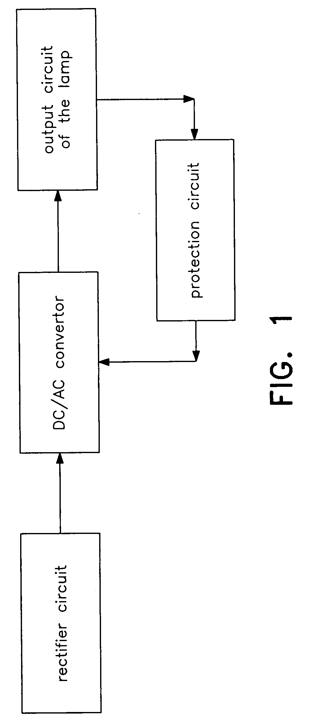
[0028]FIG. 1 shows a block diagram of an electronic ballast. It consists of a rectifier circuit, a DC / AC convertor, an output circuit of the lamp and a protection circuit. Said DC / AC convertor includes an inner trigger circuit used for start trigger to the DC / AC convertor. Said protection circuit is connected between the DC / AC convertor and the output circuit of the lamp, and makes the lamp tube stop oscillating when abnormality occurs.

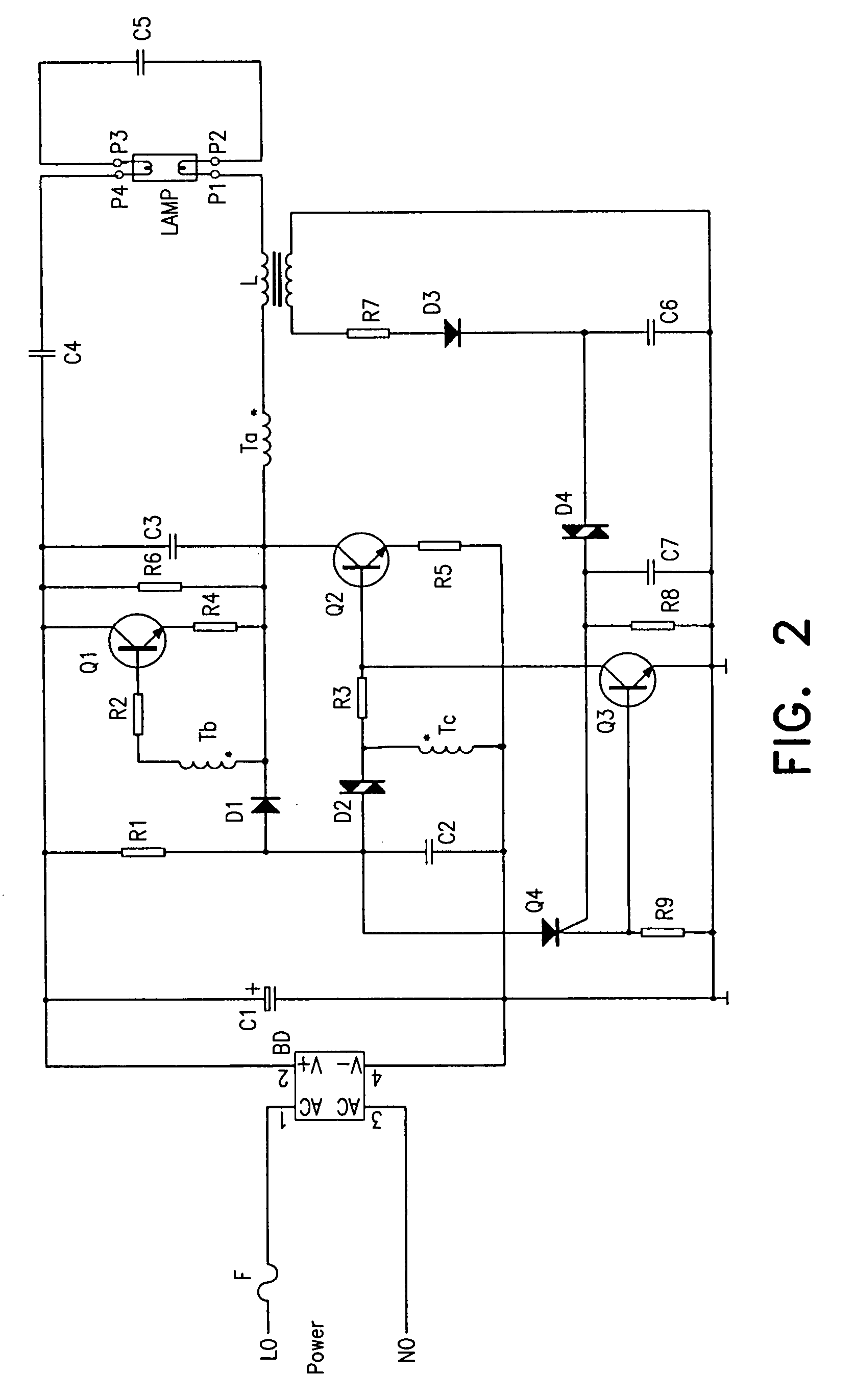
[0029]FIG. 2 shows a schematic diagram of an existing electronic ballast. It also includes a rectifier circuit, a DC / AC convertor, an output circuit of the lamp and a protection circuit. It is limited in practical application because it adopts the meaning of continuous trigger and the protection circuit without automatic start, which is mentioned above and is unnecessary to repeat.

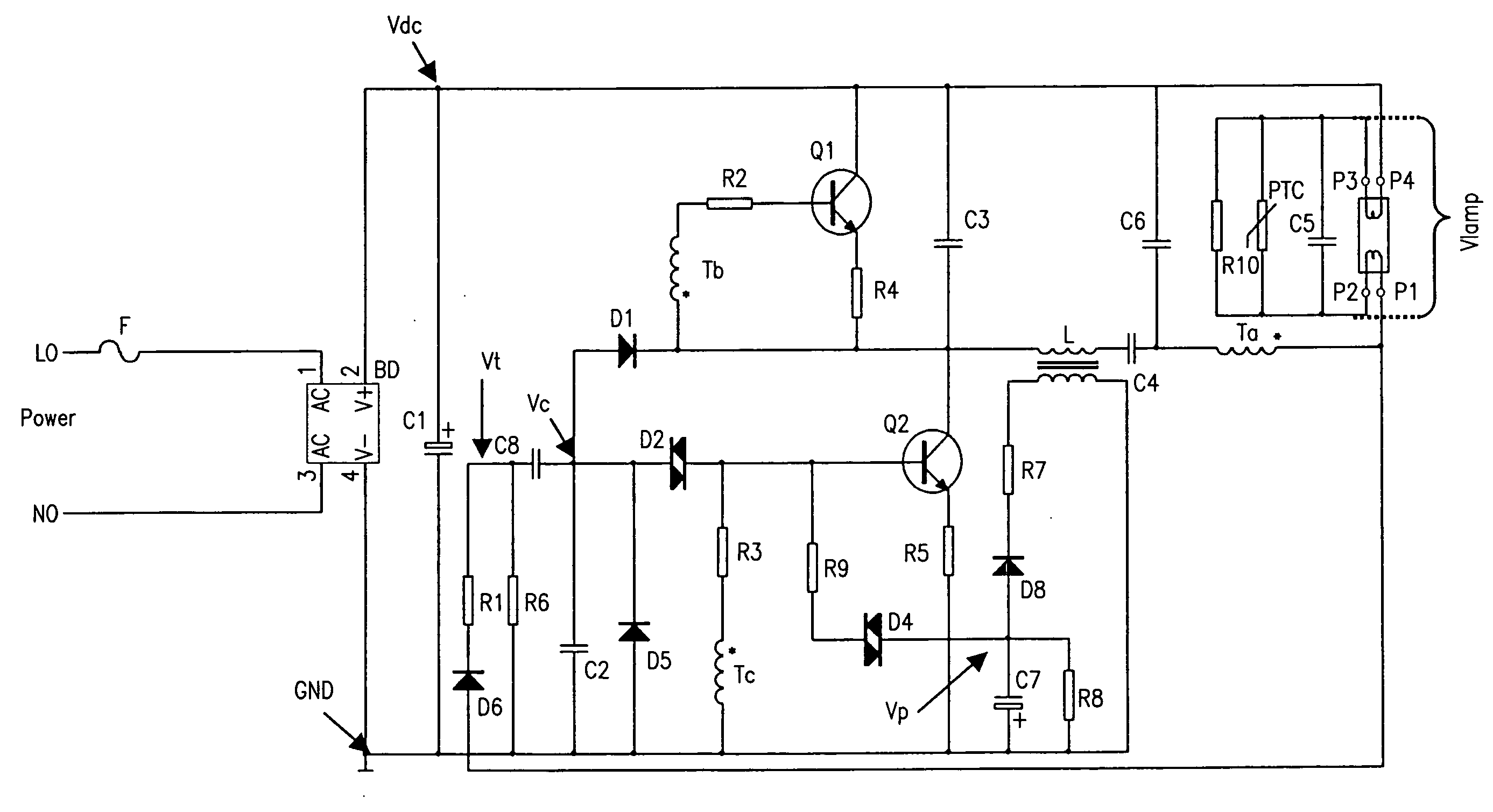
[0030]FIG. 3 shows a schematic diagram of an electronic ballast with capability of automatic restart of the present invention. It includes a fuse F, a rectifier BD, a filt...


PUM


Abstract

This present invention discloses a circuit of the electronic ballast with the capability of automatic restart. It includes a rectifier circuit, a trigger circuit of automatic restart, a DC/AC convertor, a output circuit of the lamp, and a circuit of abnormal protection. Its main feature is that there is a discharge loop in the trigger circuit, so it can realize automatic restart only after changing the lamp tube or connecting the lamp pin without turning off the power source when the lamp tube is abnormal and enters into protecting condition or any of the lamp pins is in poor contact. Because the trigger recourse Vt is led out from the lamp loop, when the power source is switched on, the DC/AC convertor is triggered to start after insuring good contact between the lamp tube and the lamp holder, accordingly realizes the self-check function of the connection for the lamp tube. Furthermore, because primary side winding Ta of oscillating coil T of the present invention is connected in series between the lamp pin P1 and the common end of feed-through capacitor C4 and by-pass capacitor C6, the primary side winding Ta of oscillating coil T will disconnect the power source when the lamp is in open circuit or any of the lamp pins is in poor contact. Therefore, the circuit will not come into protecting condition despite the by-pass capacitor C6, which results in the simplification of the task program.

Description

FIELD OF THE INVENTION [0001] This invention relates to the field of power electron and illuminative electron, particularly to the field of electronic ballast for the fluorescent lamp. DESCRIPTION OF THE RELATED ART [0002] In the application technology of the electronic ballast for the fluorescent lamp, the circuit of the electronic ballast generally comprises the circuits of rectifier, DC / AC convertor, output, abnormal protection etc. Thereinto, the part of DC / AC convertor comprises a trigger start circuit while the abnormal protection circuit is connected between the output circuit and DC / AC convertor (referring to FIG. 1). [0003] Conventionally (referring to FIG. 2), the trigger of DC / AC convertor is generally a type of continuous trigger. However, the abnormal protection circuit mostly comprises more complicated circuits. In FIG. 2, a resistance R1, a diac D2, a capacitor C2 and a diode D1 constitute the trigger circuit; a secondary side winding of output inductance L1, a resist...

Claims


Application Information

Patent Timeline
Patent Type & Authority Applications(United States)
IPC IPC(8): H05B41/36
CPCH05B41/2855Y02B20/185H05B41/2985Y02B20/00
Inventor ZENG, HAORAN
Owner DONGYANG TOSPO LIGHTING
Why Eureka
Try Eureka