Programmable Controller

a programmable controller and controller technology, applied in the field of sequence control, can solve the problems of increasing actual problems, difficult to say that the required time taken to detect abnormalities such as the aforementioned short-circuit can be shortened sufficiently, and the effect of increasing the actuality of problems such as this

Active Publication Date: 2008-04-03
JTEKT CORP
View PDF0 Cites 3 Cited by
  • Summary
  • Abstract
  • Description
  • Claims
  • Application Information

AI Technical Summary

Benefits of technology

[0045](2) It becomes possible to limit the interfaces between the circuit group on the diagnosing side and the circuit group on the diagnosed side to optical interfaces only. Thus, inde

Problems solved by technology

On the contrary, when the input signals from the switch SW1 and the switch SW0 of the two systems do not coincide, such is judged to be the occurrence of an abnormality, in which event an abnormality stop, that is, an emergency stop is performed to emergently stop all the output devices in a moment.
Therefore, the present situation is that it is hard to say that a req

Method used


Image

  • Programmable Controller
  • Programmable Controller
  • Programmable Controller

Examples


first embodiment

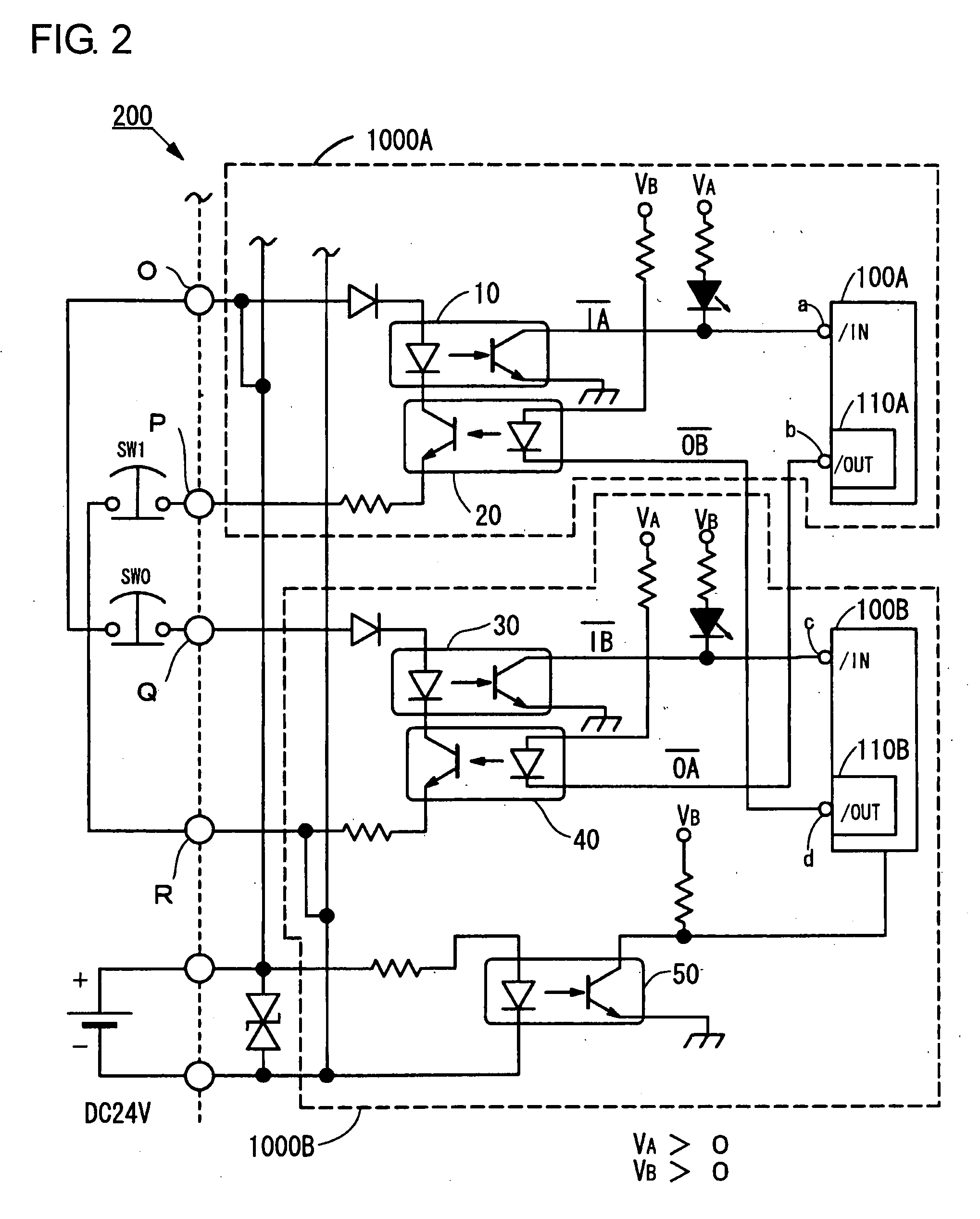
[0067]FIG. 2 shows an input circuit 200 of a programmable controller in the first embodiment. Input terminals O and P constitute first input terminals by these two terminals. Further, likewise, input terminals Q and R constitute second input terminals. Switches SW1 and SW0 are those duplexing a manual emergency stop button, and when the emergency stop button is pushed, both of the switches SW1 and SW0 are opened simultaneously. That is, when the emergency stop button is pushed, electrical connection is cut off both between the input terminals O, Q and between the input terminals P, R. The emergency stop button is one representing an external input device, and in fact, a plurality of other external input devices (not shown) are arranged and connected in the same manner as the emergency stop button in parallel relation with the emergency stop button. The external input devices are optional, and there are connectable contacts of various kinds such as, for example, switches, limit switc...

first modification

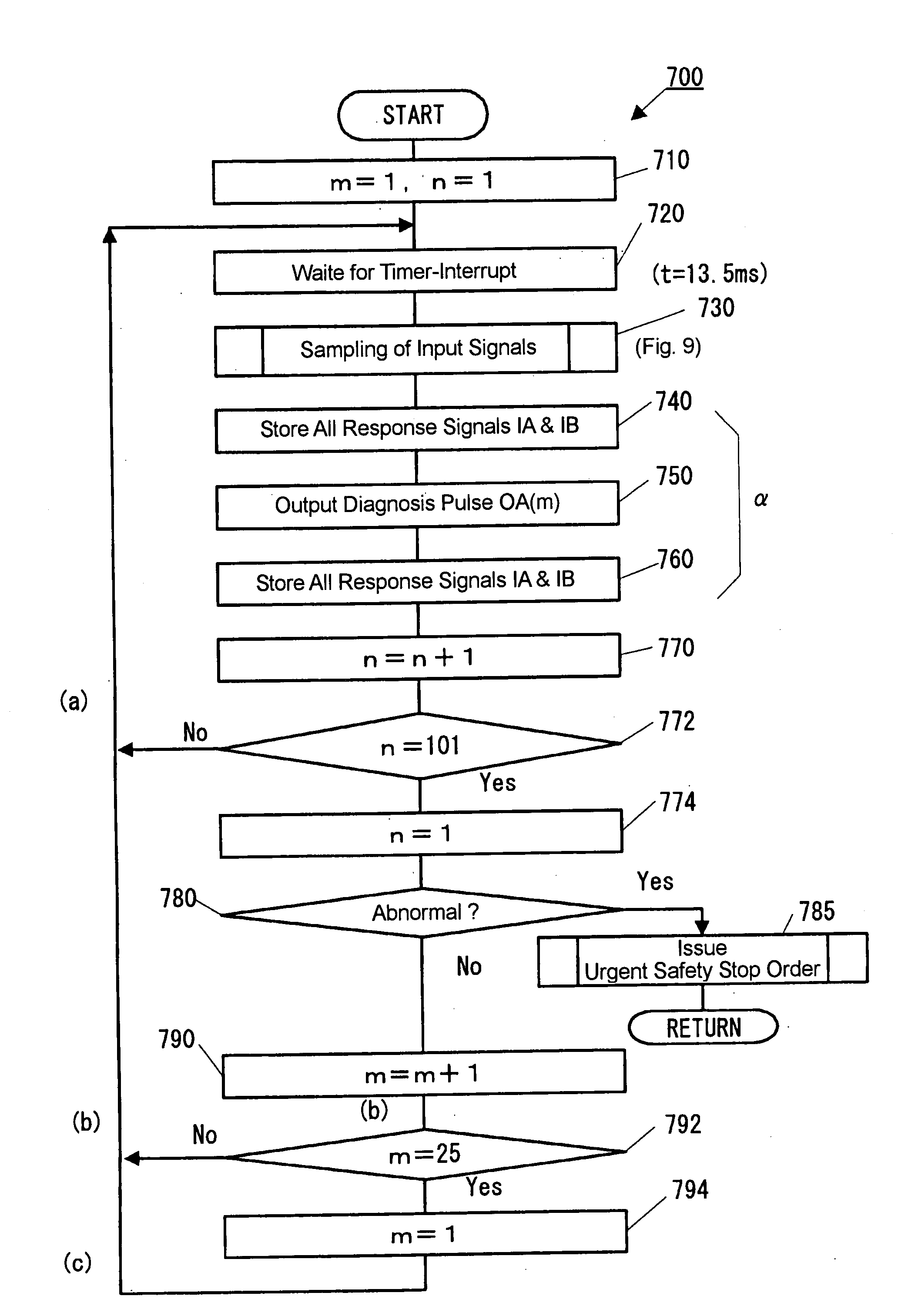
[0139]For example, in the self-diagnosis (FIG. 7) in the aforementioned first embodiment, all the bits of the response signal IA are stored every time respectively in the predetermined evacuation areas at step 350. However, in dependence on the judgment method at the subsequent step 380, it is not necessarily required to do so.

[0140]The step 540A (FIG. 9) and the step 540B (FIG. 10) are configured by utilizing a judgment criterion that if a signal of the value “0” (OFF signal indicative of the interruption of the input) is inputted even once of the five times, that bit is judged to be “0”. For example, it may be the case that by utilizing the judgment criterion adequately, it becomes possible to dynamically execute the most part of the judgment processing, so that the evacuation areas for reference data (input signals) can be suppressed to the minimum.

second modification

[0141]Further, although in the foregoing first embodiment, the duplexing of the input circuit has been practiced with the two systems separately including the A-system and the B-system, the multiplexing of the input circuit may be realized in a triplexing form or may be realized in a quadruplexing form. For example, where the input circuit is triplexed by three systems including the A-system, the B-system and the C-system, it becomes possible to apply the majority theory to the non-coincidence detection processing method in the non-coincidence detection means or to dynamically reduce the triplexed system to the duplexed system where an abnormality occurs in one system only. Therefore, it becomes also possible to greatly reduce the chances for the system stops.

[0142]By constructing the means in the present invention properly, it is possible to lead the operation of the present invention regardless of the multiplexing of these means. That is, the substantive operation principle of the...


PUM


Abstract

While a microcomputer 100A is executing a self-diagnosis (A), second diagnosis pulse output means 110B of a B-system microcomputer 100B is not used utterly. Further, during this time, the B-system microcomputer 100B does not execute a processing relating to at least the self-diagnosis (A) utterly. By shifting the timings for the A-system and the B-system to output the diagnosis pulses, independencies can be secured between respective diagnosis processing (self-diagnoses (A) and (B)). Thus, the independencies between the A-system and the B-system can be verified briefly by the self-diagnosis (A) on the A-system side. Further, first diagnosis pulse group are outputted parallel and simultaneously from first diagnosis pulse output means 110A. Thus, since cyclic control is not required for respective external input devices, it can be done to verify the independencies between the A-system and the B-system within a short period of time.

Description

TECHNOLOGICAL FIELD[0001]The present invention relates to a sequence control for the operations of a robot, a machine tool and peripheral devices therefor and particularly, is very useful in highly securing the reliability and safeness in the processing for input signals inputted to a programmable controller (PLC).BACKGROUND ART[0002]There is a system wherein a programmable controller performs the sequence control like that aforementioned above. In recent years, there is becoming widespread a PLC (so-called safety PLC) of an independent construction which is specialized for the safety management of the system in detecting the abnormality and the emergency state of the system as well as in automatically performing an emergency safety stop of the system. Patent Documents 1 and 2 noted below exemplify technologies relating to a so-called safety PLC like this.[0003]As one of other technologies, FIG. 14 exemplifies a circuit diagram (in normal state) of a known input circuit 201 which is...

Claims


Application Information

Patent Timeline
IPC IPC(8): G06F19/00G05B9/02G05B19/05
CPCG05B9/03G05B19/058G05B2219/1184G05B2219/1186G05B2219/1189G05B2219/1195G05B2219/24196G05B2219/14054G05B2219/14116G05B2219/14126G05B2219/24173G05B2219/24184G05B2219/24186G05B2219/14007
Inventor KATO, SATOSHIARAKI, TSUTOMU
Owner JTEKT CORP
Why Eureka
Try Eureka