Pipe Coupling

Active Publication Date: 2008-07-03
AAGE V KJRS MASKINFAB
View PDF4 Cites 7 Cited by
  • Summary
  • Abstract
  • Description
  • Claims
  • Application Information

AI Technical Summary

Benefits of technology

[0010]The object of the present invention is to provide a pipe coupling of the above type which is simple and inexpensive to manufacture and install in a pipe system and which may be used for pipes of different diameters and diffe

Problems solved by technology

Particularly due to the large number of elements of the gripping and s

Method used


Image

  • Pipe Coupling
  • Pipe Coupling
  • Pipe Coupling

Examples


Embodiment Construction

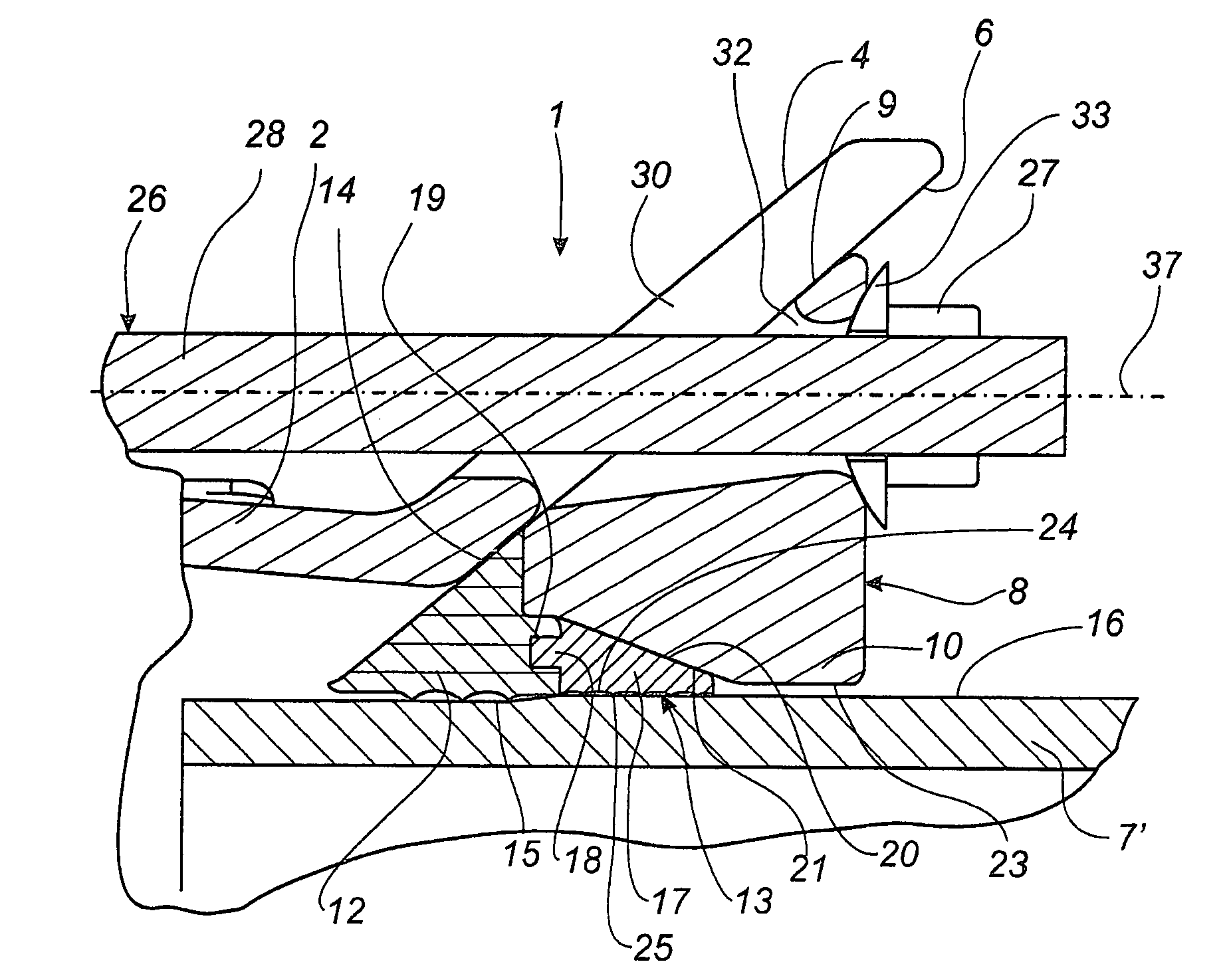
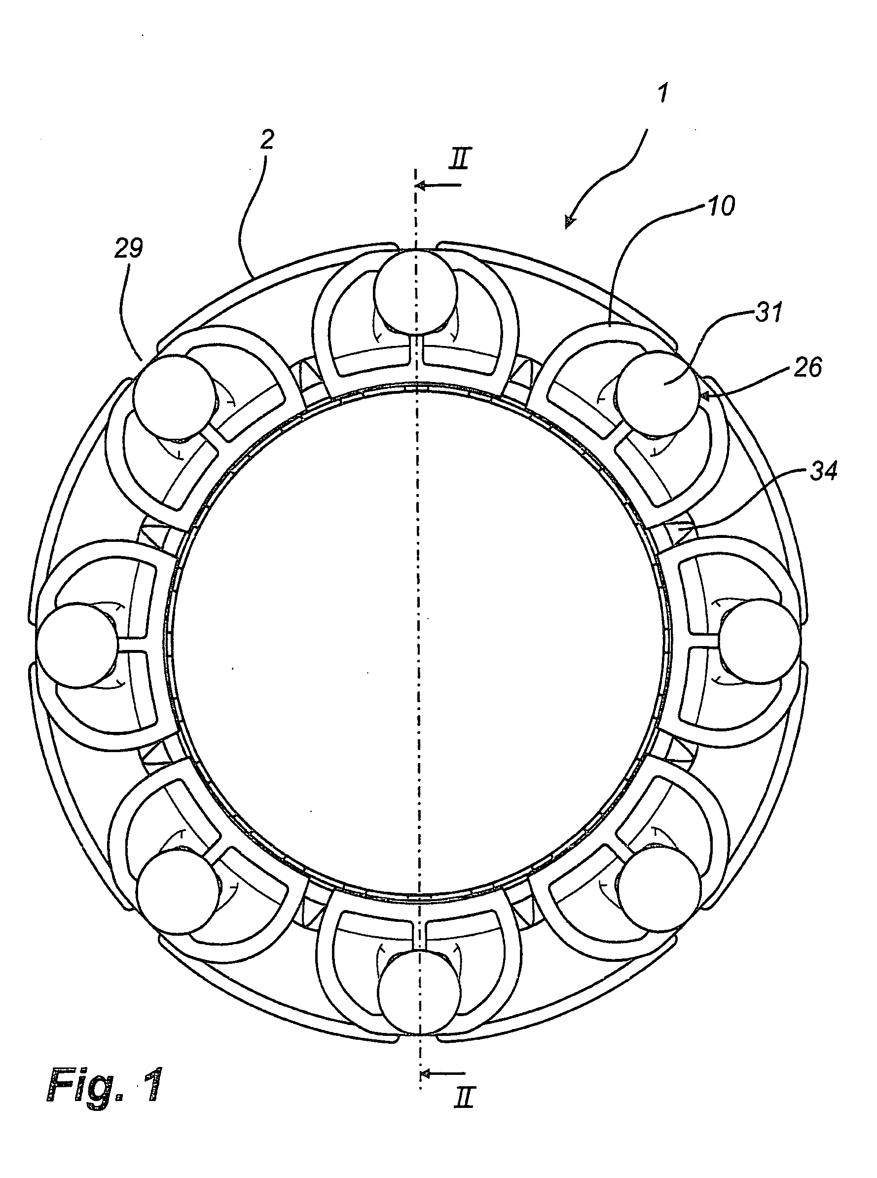
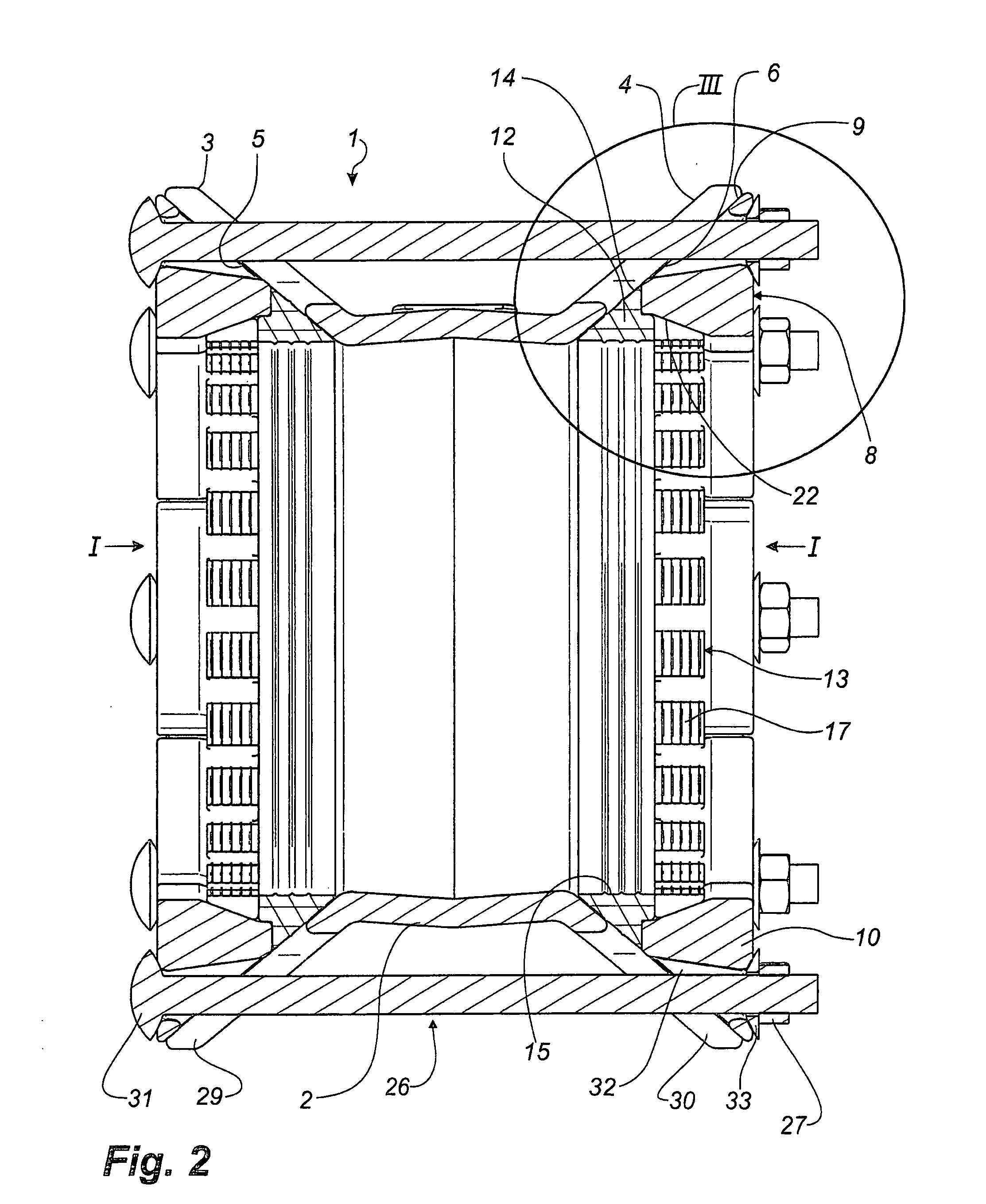
[0042]The embodiment of a pipe coupling 1 according to the invention shown in FIGS. 1 to 4 is adapted to substantially co-axially connect two pipes. The pipe coupling 1 includes a sleeve 2 being provided with an outwardly extending flange 3,4 at opposing ends, said flanges each having an end face 5, 6 tapering in the insertion direction of a pipe end which has been inserted and received in the opposing ends of the sleeve. In FIG. 2, the insertion direction of the pipe ends into the sleeve ends are indicated by means of the arrows I.

[0043]As it is appears from FIG. 2, the pipe coupling 1 is shaped substantially symmetrical about the central plane of the sleeve 2. In the description below reference is thus primarily made to the sleeve half shown on the right-hand side of FIG. 2. At each end, the pipe coupling further includes a pressure ring 8 provided with an abutment face 9 facing the end face 6 of the flange 4 in displaceable abutment therewith.

[0044]The pressure ring 8 is divided ...


PUM


Abstract

A pipe coupling (1) includes a pipe-shaped sleeve (2) being provided with a protruding flange (4) at least in one end, said flange having a tapering end face (6). The pipe coupling further including an annular gripping ring (13) divided into ring segments (17), an annular resilient sealing ring (12) provided between the flange (4) and the gripping ring (13), a pressure ring (8) and tightening means of the bolt/nut type (26, 27). The pressure ring (8) is divided into a number of separate, mutually interspaced ring segments (10) each provided with an abutment face (9) adapted to displaceably abut the end face (6) of the flange (4). The bolts (26) extend through elongated, radially extending openings (30) in the flange (4) and through clearance holes (32) in the pressure ring segments (10).

Description

TECHNICAL FIELD[0001]The invention relates to a pipe coupling comprising:[0002]An annular sleeve having at least one insertion end shaped such that a pipe end can be inserted and received therein by being inserted in an insertion direction, said sleeve being provided with a projecting flange having and end face tapering in the insertion direction of the pipe,[0003]An annular gripping means having a gripping face facing the outer face of the pipe,[0004]An annular, resilient sealing means arranged between the flange and the gripping means when seen in axial direction,[0005]An annular pressure means, and[0006]Tightening means of the bolt / nut type for pulling the sleeve and the pressure means towards each other for moving the gripping face of the gripping means and the sealing means inwards into tight-gripping and sealing engagement, respectively, with the outer face of the pipe.BACKGROUND ART[0007]Pipe couplings of the above type are used for sealingly and tension-proof interconnecting...

Claims


Application Information

Patent Timeline
IPC IPC(8): F16L21/04
CPCF16L21/08F16L21/04
Inventor FREUDENDAHL, ERLING
Owner AAGE V KJRS MASKINFAB
Why Eureka
Try Eureka