Exercise Device

Inactive Publication Date: 2009-04-30
LAMORE GEORGE
View PDF26 Cites 61 Cited by
  • Summary
  • Abstract
  • Description
  • Claims
  • Application Information

AI Technical Summary

Benefits of technology

[0027]An object of the present invention is to provide an ex

Problems solved by technology

The treatment, relief and prevention of back pain can be prohibitively costly, painful, require another individual to administer treatment or operate an associated device, and time consuming due to required travel to locations to receive treatment.
Some back injuries are so painf

Method used


Image

  • Exercise Device
  • Exercise Device
  • Exercise Device

Examples


Example

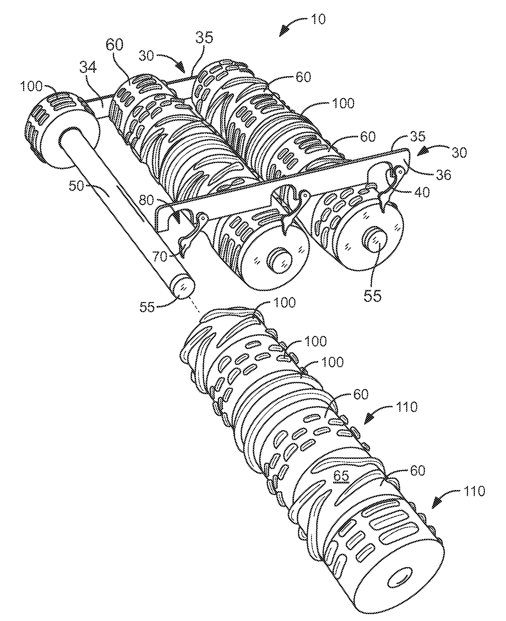
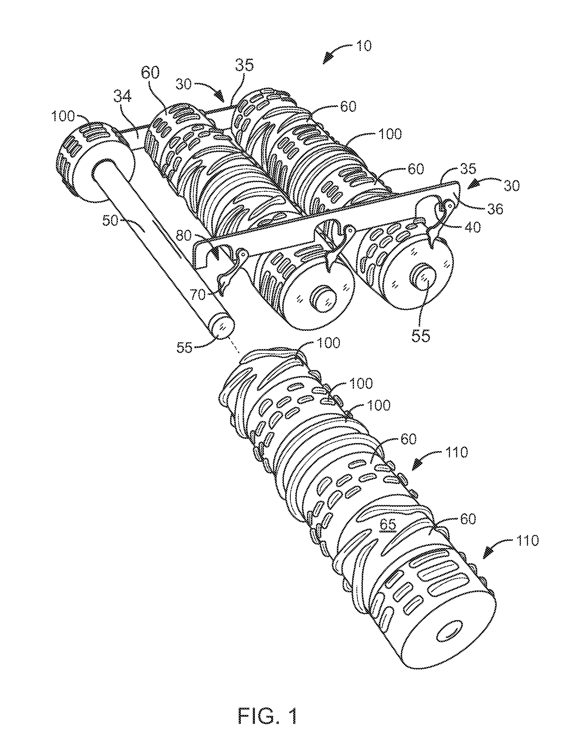
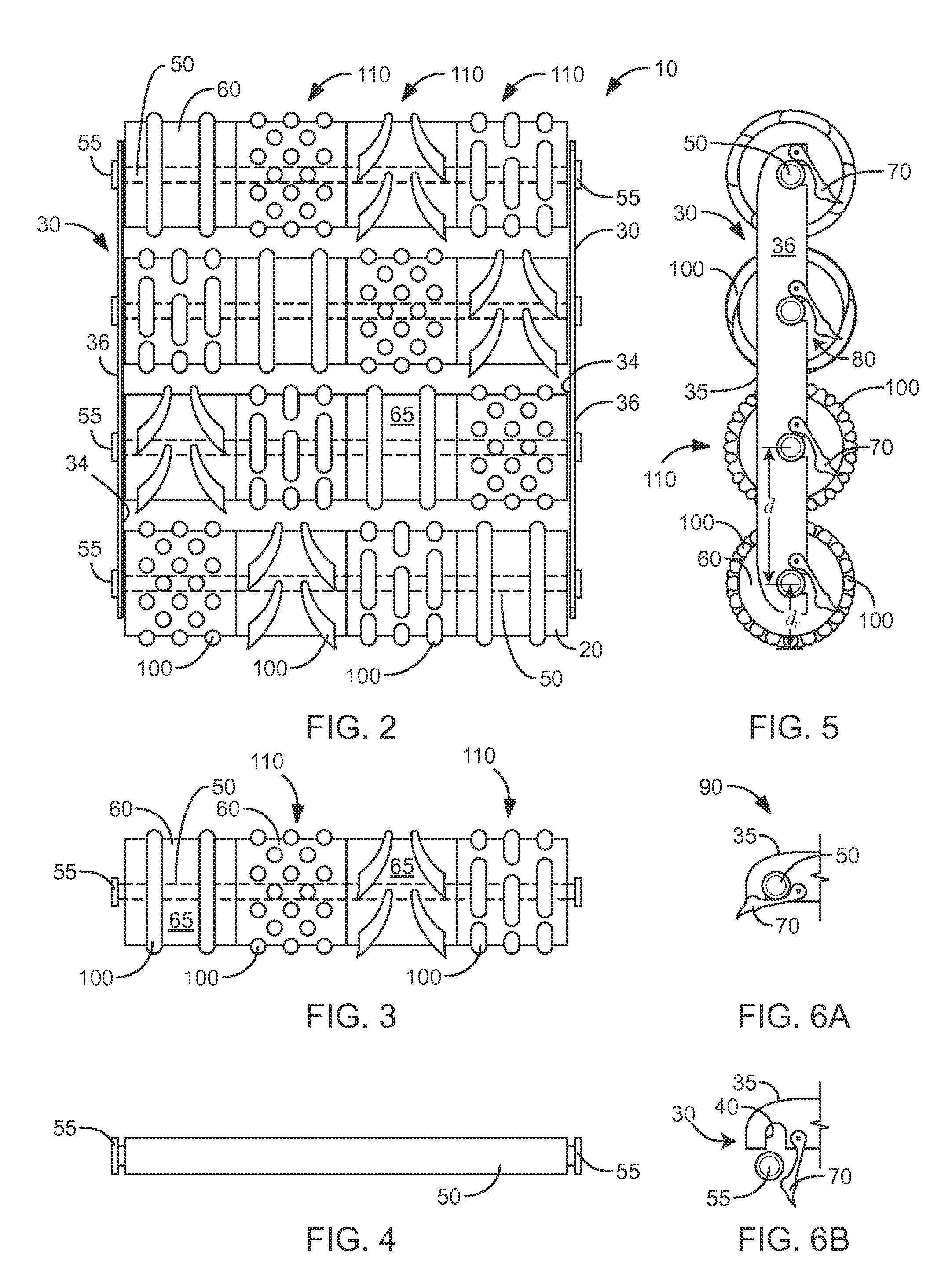
[0045]Referring now to the figures, in which like numerals indicate like parts, and particularly to FIGS. 1 through 7, the present invention will be discussed with reference thereto. An exercise device 10 for a person 20 is provided. The exercise device 10 comprises at least two substantially rigid rails 30, made of rigid plastic or metal, such as aluminum, for example. Each rail 30 has an outer surface 36, and inner surface 34, and at least one peripheral edge 35 connecting the outer surface 36 to the inner surface 34. The at least one peripheral edge 35 includes at least one axle slot 40 formed therein.

[0046]At least one substantially cylindrical axle 50 has two ends 55 and is adapted for rotatably and removably receiving at least one substantially cylindrical roller 60 thereon. Each end 55 of each axle 50 is adapted to be captured within one of the axle slots 40 of one of the rails 30. Each roller 60 has a peripheral surface 65 and a maximum diameter dr. Each axle 50 is spaced a ...


PUM


Abstract

An exercise device for a person, comprising at least two substantially rigid rails, each rail having an outer surface, and inner surface, and at least one peripheral edge connecting the outer surface to the inner surface. The at least one peripheral edge includes at least one axle slot formed therein. At least one substantially cylindrical axle has two ends and is adapted for rotatably and removably receiving at least one substantially cylindrical roller thereon. Each end of each axle is adapted to be captured within one of the axle slots of one of the rails. Each roller has a peripheral surface and a maximum diameter. Each axle is spaced a distance from an adjacent axle of at least the maximum diameter of the rollers, whereby each roller may rotate freely on the at least one axle. The exercise device is able to support a person lying on his back on the rollers on a flat surface.

Description

CROSS-REFERENCE TO RELATED APPLICATIONS[0001]Not Applicable.STATEMENT REGARDING FEDERALLY SPONSORED RESEARCH AND DEVELOPMENT[0002]Not Applicable.FIELD OF THE INVENTION[0003]This invention relates to exercise devices, and more particularly to a back and leg exercising device.DISCUSSION OF RELATED ART[0004]Numerous innovations for massaging apparatuses have been provided in the prior art that will be described. Even though these innovations may be suitable for the specific individual purposes to which they address, they differ from the present invention.[0005]A first example, U.S. Patent Office Document No. 1,572,794, Issued on Feb. 09 1926, to Hamilton teaches a massage device comprising a plurality of grooved rollers of different sizes and alternately arranged, the rollers being shaped to straddle the spine. A mechanism for retaining the rollers in spaced relation to one another, a table on which the rollers travel, and a mechanism attached to the table for guiding the movement of t...

Claims


Application Information

Patent Timeline
IPC IPC(8): A61H15/00A63B21/00
CPCA61H15/00A61H2015/0021A63B21/0004A63B2213/00A63B23/0405A63B2208/0247A63B22/20A61H15/0092A61H2201/1284A61H2201/1695
Inventor LAMORE, GEORGE
Owner LAMORE GEORGE
Why Eureka
Try Eureka