Hand Crank Generator

a generator and crank technology, applied in the direction of electrical apparatus, muscle energy, dynamo-electric machines, etc., can solve the problems of large effort consumption, constant replacement or recharge of batteries, and inability to always have sufficient electric energy, so as to save a lot of effort

Active Publication Date: 2008-07-31
TAI DANIEL
View PDF14 Cites 16 Cited by
  • Summary
  • Abstract
  • Description
  • Claims
  • Application Information

AI Technical Summary

Benefits of technology

[0006]The primary purpose of the present invention is to provide a hand crank generator that is simple in construction and allows easy operation.
[0012]The gear transmission includes a first transmission gear, a second double gear, a third double gear, and a fourth double gear; wherein the first transmission gear is fixed to the arm, the first gear engages with a pinion in the second double gear; a gearwheel of the second double gear engages with a pinion in the third double gear; a gearwheel of the third double gear engages with a pinion in the fourth double gear; and the gearwheel of the fourth double gear engage with the clutch gear. The gear transmission adopts a three-stage acceleration design to increase output revolution speed.
[0014]In the present invention, the crank is driven manually to further drive the gear transmission and then the generation motor revolves as driven by the clutch gear to generate electric current. When the manual cranking stops, the clutch gear is disengaged from the motor gear on the generation motor; however, given with the inertia provided by the weight wheel, the motor gear continues to revolve to drive the generation motor to keep generating electric current. Accordingly, a user may save lots of efforts. Furthermore, the present invention may be connected to an energy accumulator like a battery to become another product with different application when the present invention is connected to a electricity input end of a light emitting object or other electric appliance through the energy accumulator like a battery.

Problems solved by technology

Those battery dependent products though permit easy portability and convenient use, battery must be continuously replaced or recharged due to limited storage capacity of the battery.
As a result, these electric appliances are not necessarily always readily available; and that could be a problem particularly for those who spend much time on the road.
Accordingly, to generate more power, a great effort must be consumed to exchange for sufficient electric energy.

Method used


Image

  • Hand Crank Generator
  • Hand Crank Generator
  • Hand Crank Generator

Examples


Embodiment Construction

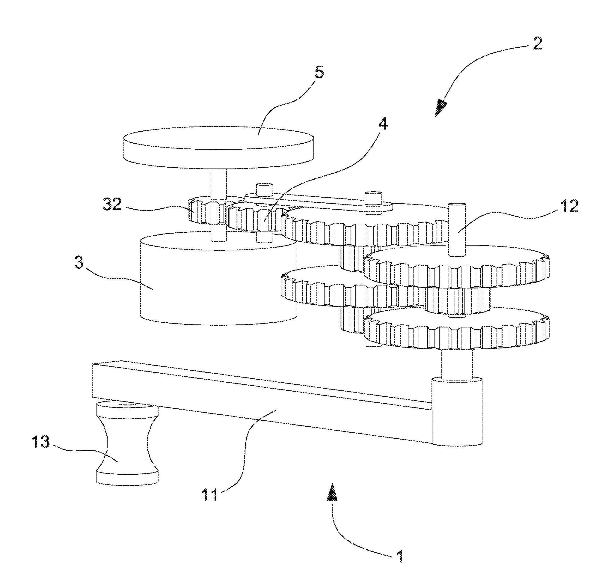
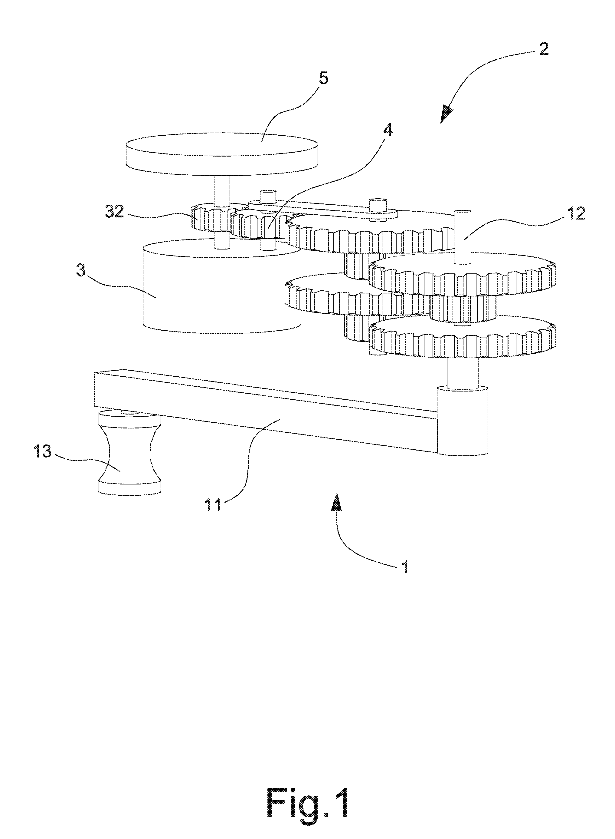
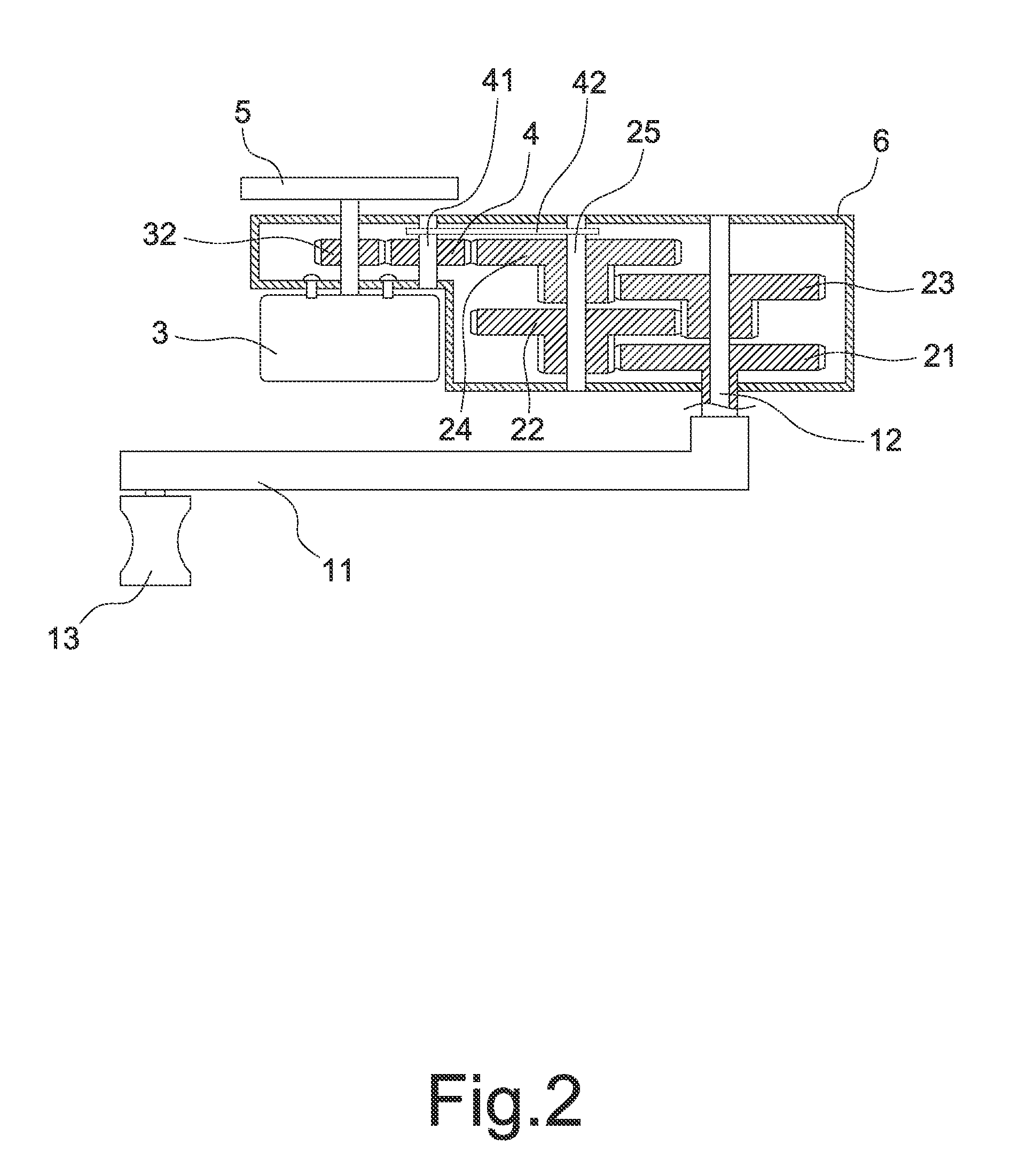
[0021]Referring to FIGS. 1 and 2 for a preferred embodiment of the present invention, a hand crank generator of the present invention is comprised of a crank 1, a gear transmission 2, a generation motor 3, a clutch gear 4, and a weighted wheel 5. Wherein, the gear transmission 2 is mounted in a box 6; the crank 1 is connected to an input end of the gear transmission 2 to drive the gear transmission 2; the clutch gear 4 is located at an output end of the gear transmission 2 and engages with a motor gear 32 disposed on a central shaft 31 of the generator motor 3 to drive the generation motor 3 to revolve for generating electric current; and the crank 1 is provided with an arm 11 and a handle 13 with the handle mounted to one end of the arm 11.

[0022]The gear transmission 2 of the preferred embodiment is essentially comprised of a first transmission gear 21, a second double gear 22, a third double gear 23, and a fourth double gear 24. Wherein, the first transmission gear 21 and the thir...


PUM


Abstract

A hand crank generator includes crank, gear transmission, and generation motor driven by the gear transmission. The crank and the gear transmission are coupled to each other. A clutch gear is coupled to where between the crank and the gear transmission. The crank is manually driven to further drive the gear transmission, and the generation motor is driven to generate electric current through the clutch gear. When the cranking stops, the clutch gear disengages from a motor gear disposed on the generation motor. A weighted wheel continues to revolve under inertia to drive the generation motor to keep on generating electric current without continuing to crank; therefore, achieving the purpose of saving manual efforts.

Description

BACKGROUND OF THE INVENTION[0001](a) Field of the Invention[0002]The present invention is related to a hand crank generator, and more particularly, to one that is applied in small sized electric appliances.[0003](b) Description of the Prior Art[0004]Small size electric appliances, e.g., flashlight, battery charger, are indispensable in our daily life; however, so far all these small sized electric appliances must use batteries or connection to a power source to operate. Those battery dependent products though permit easy portability and convenient use, battery must be continuously replaced or recharged due to limited storage capacity of the battery. As a result, these electric appliances are not necessarily always readily available; and that could be a problem particularly for those who spend much time on the road. To correct this problem, a hand crank generator is introduced into the market.[0005]The hand crank generator of the prior art operates by cranking to drive gears to rotat...

Claims


Application Information

Patent Timeline
Patent Type & Authority Applications(United States)
IPC IPC(8): H02K7/116H02K7/18
CPCH02K7/1861H02K7/116F03G5/06H02K7/10Y10T74/19367Y10T74/19614
Inventor DAI, JEN HAO
Owner TAI DANIEL
Why Eureka
Try Eureka