Fuel cell stack

a fuel cell and stack technology, applied in the direction of fuel cells, fuel cells, solid electrolyte fuel cells, etc., can solve the problem of not being able to apply the desired electrode load, and achieve the effect of simple and economical structure and stress reduction

Active Publication Date: 2008-09-25
HONDA MOTOR CO LTD
View PDF4 Cites 1 Cited by
  • Summary
  • Abstract
  • Description
  • Claims
  • Application Information

AI Technical Summary

Benefits of technology

[0012]A main object of the present invention is to provide a fuel cell stack which makes it possible to apply a uniform surface pressure to the entire power generation surface (area) of the electrode, and achieve stress reduction with simple and economical structure.
[0015]In the present invention, the hinge mechanism for coupling the end plates and the side plates are dimensioned such that the hinge mechanism falls within the size of the power generation area of the electrode. With the simple and economical structure, it is possible to apply the uniform surface pressure over the entire surface of the power generation area reliably, and achieve the uniform load balance and stress reduction. As a result, the strength of the casing is optimized, and the size of the fuel cell stack is minimized advantageously.

Problems solved by technology

Under the circumstances, it is not possible to apply the desired electrode load over the entire power generation surface 8 suitably.

Method used


Image

  • Fuel cell stack
  • Fuel cell stack
  • Fuel cell stack

Examples


first embodiment

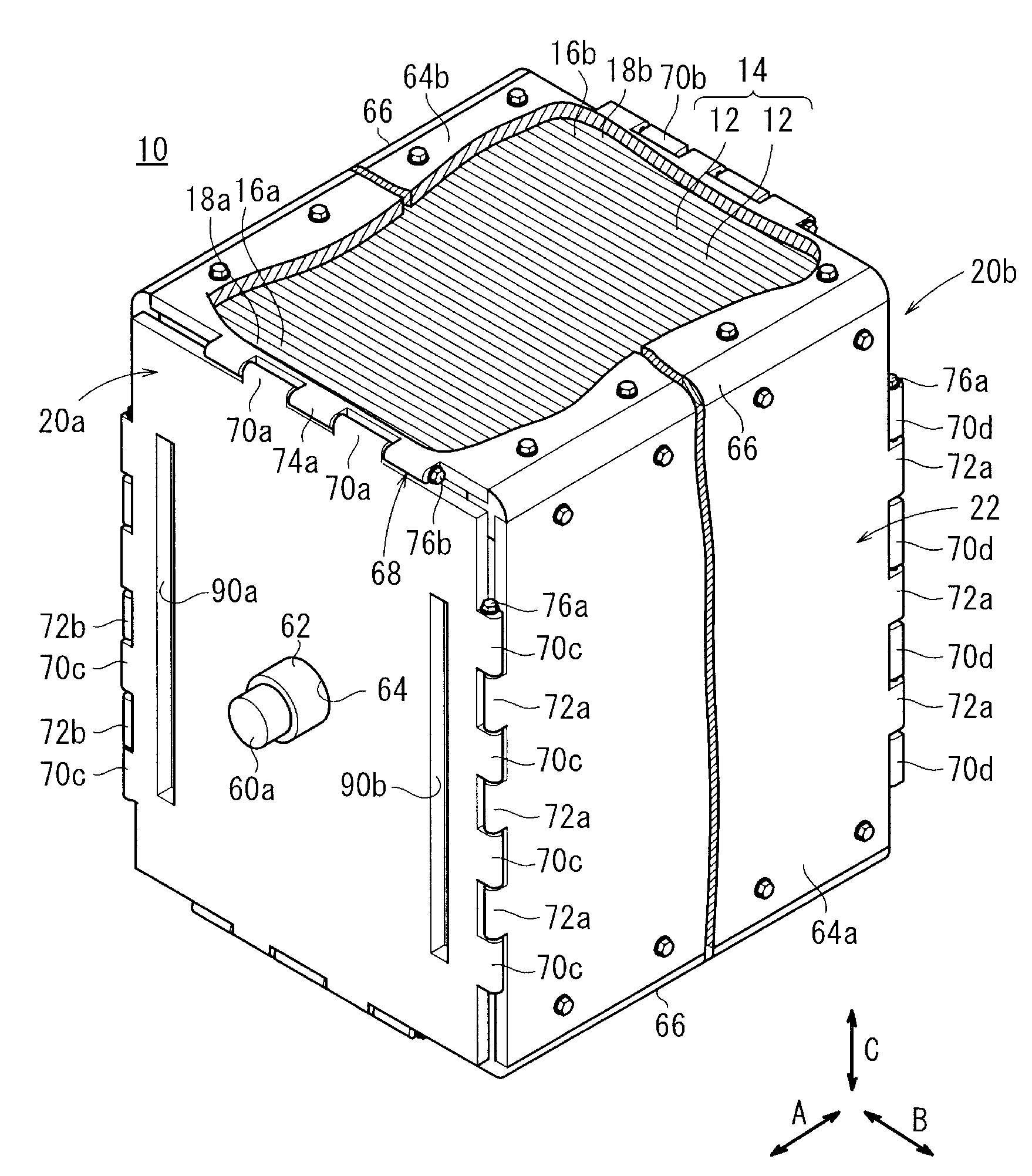
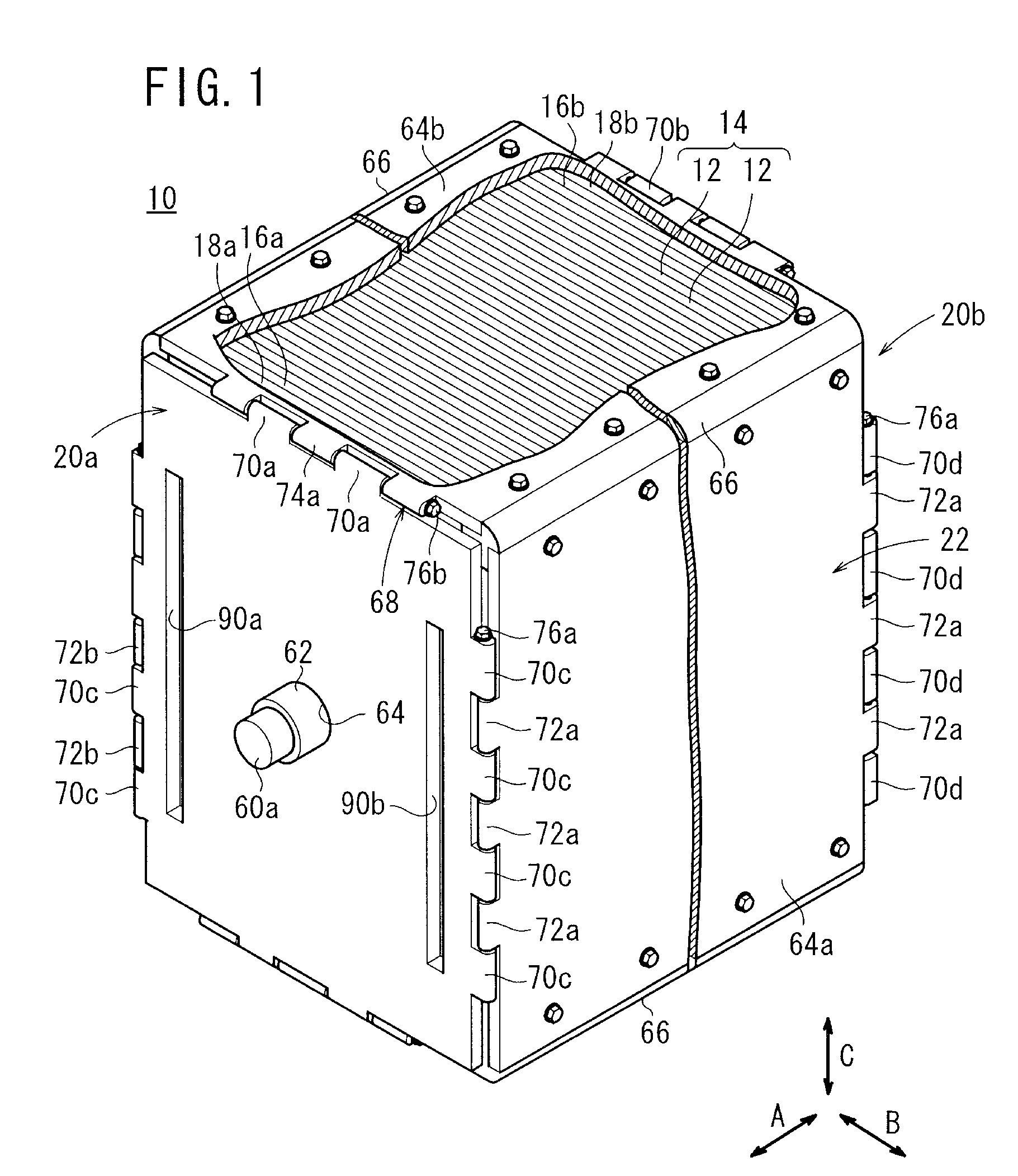
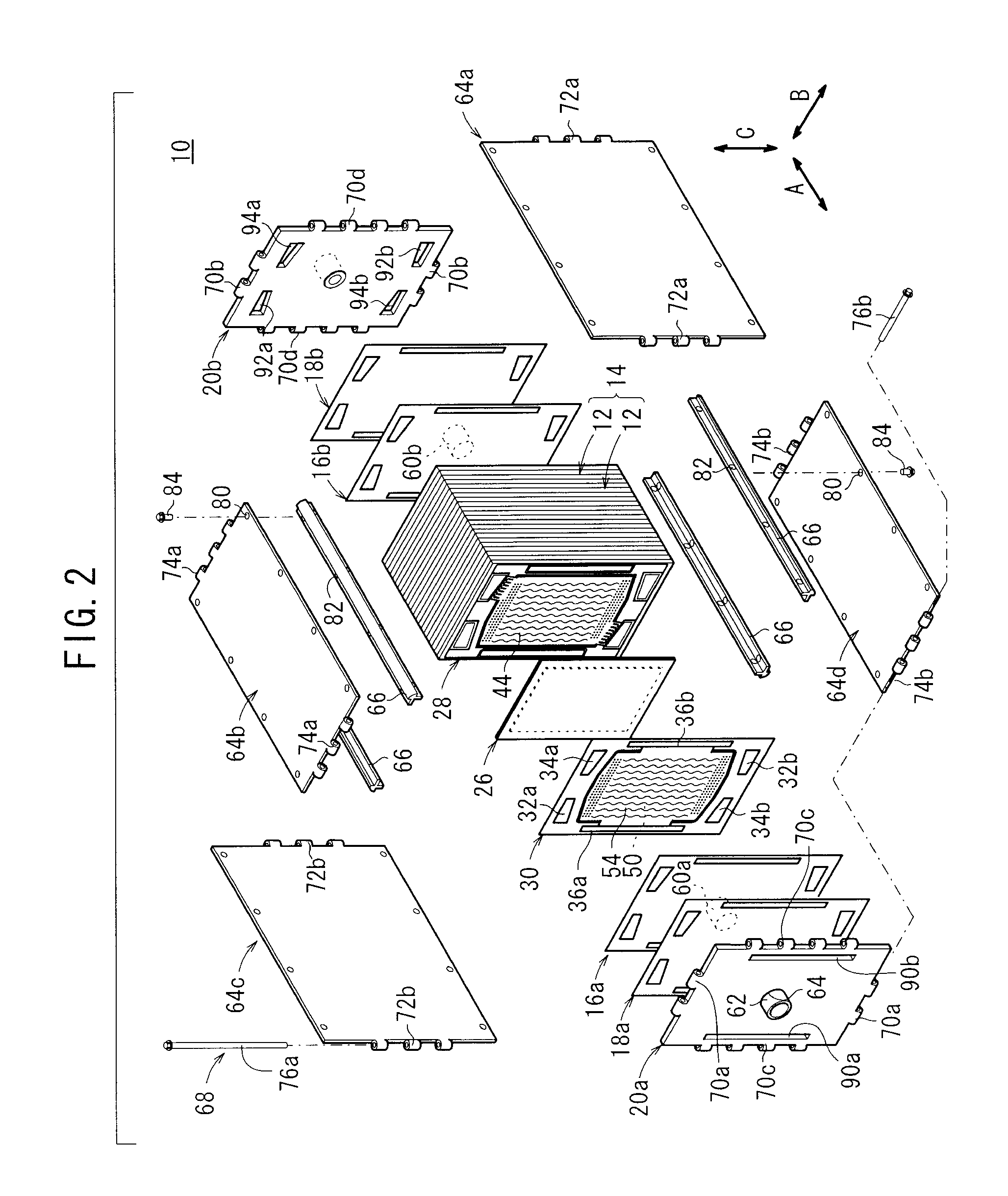
[0023]FIG. 1 is a partial-broken perspective view schematically showing a fuel cell stack 10 according to the present invention, and FIG. 2 is a partial exploded perspective view schematically showing the fuel cell stack 10.

[0024]The fuel cell stack 10 includes a stack body 14 formed by stacking a plurality of unit cells 12 horizontally in a direction indicated by an arrow A. At one end of the stack body 14 in the stacking direction indicated by the arrow A, a terminal plate 16a is provided. An insulating plate 18a is provided outside the terminal plate 16a, and an end plate 20a is provided outside the insulating plate 18a. At the other end of the stack body 14 in the stacking direction, a terminal plate 16b is provided. An insulating plate 18b is provided outside the terminal plate 16b, and an end plate 20b is provided outside the insulating plate 18b. The fuel cell stack 10 is placed in a casing 22 having the rectangular end plates 20a, 20b.

[0025]As shown in FIG. 3, each of the u...

second embodiment

[0061]In the second embodiment, two or four coolant supply passages 36a are provided at one end in the direction indicated by the arrow B, and two or four coolant discharge passages 36b are provided at the other end in the direction indicated by the arrow B.

[0062]A casing 102 of the fuel cell stack 100 has a hinge mechanism 104. In the hinge mechanism 104, a plurality of first hinges 70c, 70d are provided on both of the left and the right sides of the end plates 20a, 20b, and the first hinges 70c, 70d are separated by providing spaces 106a, 106b at vertically substantially central positions. In the side plates 64a, 64c, second hinges 72a, 72b and the first hinges 70c, 70d are provided alternately, and likewise, the second hinges 72a, 72b are vertically separated into two parts by the spaces 106a, 106b.

[0063]Coupling pins 108a are inserted into the first hinges 70c, 70d and the second hinges 72a, 72b on the upper side, and coupling pins 108b are inserted into the first hinges 70c, 7...


PUM

PropertyMeasurementUnit
sizeaaaaaaaaaa
areaaaaaaaaaaa
lengthaaaaaaaaaa

Abstract

A casing includes end plates, side plates, and a hinge mechanism for coupling the end plates and the side plates. A power generation area is defined by the distance L1 and the distance L2. When first hinges and second hinges of the hinge mechanism are provided alternately, the first hinges and the second hinges are positioned within the distance L1. Preferably, the length of the shaft of a coupling pin is not more than the length L1. When the first hinges and the second hinges are provided alternately, the first hinges and the second hinges are positioned within the length L2. Preferably, the length of the shaft of a coupling pin is not more than the length L2.

Description

BACKGROUND OF THE INVENTION[0001]1. Field of the Invention:[0002]The present invention relates to a fuel cell stack including a stack body formed by stacking a plurality of unit cells in a stacking direction and a box-shaped casing containing the stack body. Each of the unit cells includes an electrolyte electrode assembly and separators sandwiching the electrolyte electrode assembly. The electrolyte electrode assembly includes a pair of electrodes and an electrolyte interposed between the electrodes.[0003]2. Description of the Related Art:[0004]For example, a solid polymer electrolyte fuel cell employs an electrolyte membrane (electrolyte) comprising a polymer ion exchange membrane. The electrolyte membrane is interposed between an anode and a cathode to form a membrane electrode assembly. The membrane electrode assembly is sandwiched between separators to form a fuel cell.[0005]In use, normally, a predetermined number of (e.g., several tens to several hundreds of) fuel cells are s...

Claims


Application Information

Patent Timeline
Patent Type & Authority Applications(United States)
IPC IPC(8): H01M2/02
CPCH01M8/2475Y02E60/50H01M8/248
Inventor YOSHITOMI, RYOICHIISHIZUKA, AYUMU
Owner HONDA MOTOR CO LTD
Why Eureka
Try Eureka