

Method of blocking a portion of illumination rays generated by a countertop-supported digital imaging system, and preventing illumination rays from striking the eyes of the system operator or nearby consumer during operation of said countertop-supported digital image capture and processing system installed at a retail point of sale (POS) station
a digital imaging and countertop technology, applied in the field of area-type digital image capture and processing systems, can solve the problems of not enabling users to read high-density 1d bar codes with ease and simplicity, not enabling end-users to modify the features and functionalities of such prior art systems without detailed knowledg
- Summary
- Abstract
- Description
- Claims
- Application Information
AI Technical Summary
Benefits of technology
Problems solved by technology
Method used
Image

Examples
Embodiment Construction
[0283]Referring to the figures in the accompanying Drawings, the various illustrative embodiments of the hand-supportable and countertop-supportable digital image capture and processing systems of the present invention will be described in great detail, wherein like elements will be indicated using like reference numerals.
Hand-Supportable / Countertop-Supportable Digital Image Capture and Processing System of the First Illustrative Embodiment of the Present Invention
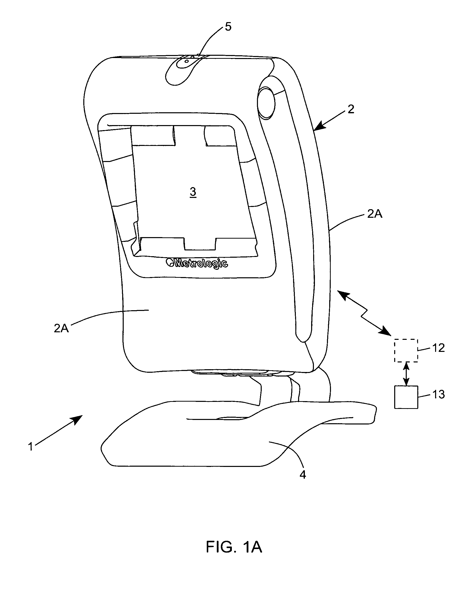
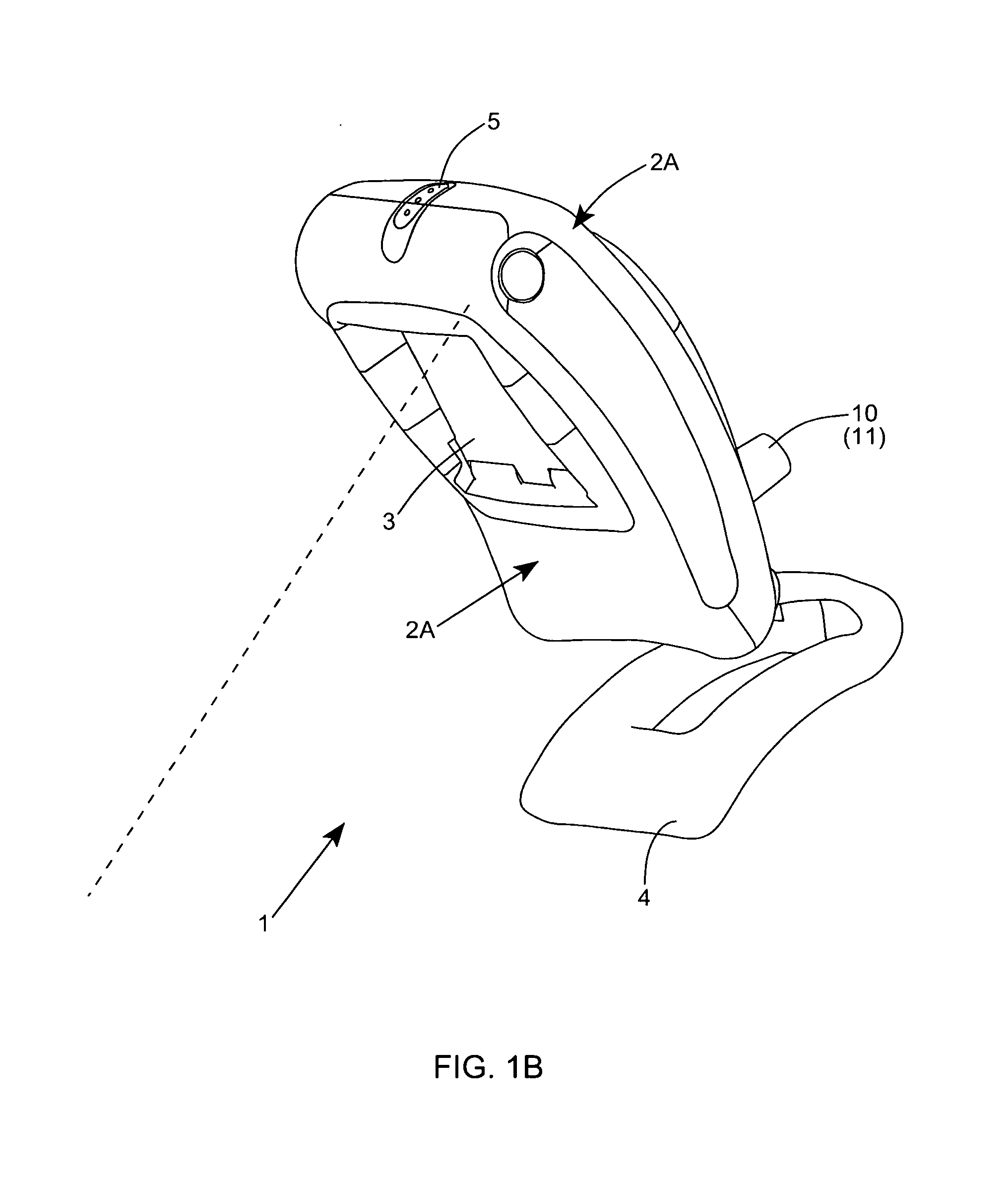
[0284]Referring to FIGS. 1A through 1F, the hand-supportable / countertop-supportable digital image capture and processing system of the first illustrative embodiment of the present invention 1 is shown in detail comprising a hand-supportable and countertop-supportable housing 2 having a rear housing portion 2a and a front housing portion 2B that is provided with a light transmission (i.e. imaging) window 3. As best shown, digital image capture and processing system further comprises: a foot-like structure 4 mounted to the r...
PUM
 Abstract
Description
Claims
Application Information