Digital image capture and processing system supporting a periodic snapshot mode of operation wherein during each image acquistion cycle, the rows of image detection elements in the image detection array are exposed simultaneously to illumination

a digital image and processing system technology, applied in the field of area-type digital image capture and processing systems, can solve the problems of not enabling end-users to modify the features and functionalities of such prior art systems without detailed knowledge, and failing to enable users to precisely identify which portions of fov

Active Publication Date: 2008-11-20
METROLOGIC INSTR
View PDF99 Cites 3 Cited by
  • Summary
  • Abstract
  • Description
  • Claims
  • Application Information

AI Technical Summary

Benefits of technology

[0052]Accordingly, a primary object of the present invention is to provide a novel method of and apparatus for enabling the reading of 1D and 2D bar code symbologies using image capture and processing based systems and devices, which avoid the shortcomings and drawbacks of prior art methods and apparatus.
[0053]Another object of the present invention is to provide a novel hand-supportable digital image capture and processing system capable of automatically reading 1D and 2D bar code symbologies using advanced illumination and imaging techniques, providing speeds and reliability associated with conventional laser scanning bar code symbol readers.

Problems solved by technology

As a result of limitations in the field of view (FOV) marking, targeting and pointing subsystems employed within prior art digital image capture and processing systems, such prior art readers generally fail to enable users to precisely identify which portions of the FOV read high-density 1D bar codes with the ease and simplicity of laser scanning based bar code symbol readers, and also 2D symbologies, such as PDF 417 and Data Matrix.
Also, as a result of limitations in the mechanical, electrical, optical, and software design of prior art digital image capture and processing systems, such prior art readers generally: (i) fail to enable users to read high-density 1D bar codes with the ease and simplicity of laser scanning based bar code symbol readers and also 2D symbologies, such as PDF 417 and Data Matrix, and (iii) have not enabled end-users to modify the features and functionalities of such prior art systems without detailed knowledge about the hard-ware platform, communication interfaces and the user interfaces of such systems.
Also, control operations in prior art image-processing bar code symbol reading systems have not been sufficiently flexible or agile to adapt to the demanding lighting conditions presented in challenging retail and industrial work environments where 1D and 2D bar code symbols need to be reliably read.
Prior art digital imaging and laser scanning systems also suffering from a number of other problems as well.
Some prior art imaging systems have relied on IR-based object detection using the same image sensing array for detecting images of objects, and therefore, require that the decode microprocessor be powered up during the object detection state of operation, and consuming power which would be undesirable in portable digital imaging applications.

Method used


Image

  • Digital image capture and processing system supporting a periodic snapshot mode of operation wherein during each image acquistion cycle, the rows of image detection elements in the image detection array are exposed simultaneously to illumination
  • Digital image capture and processing system supporting a periodic snapshot mode of operation wherein during each image acquistion cycle, the rows of image detection elements in the image detection array are exposed simultaneously to illumination
  • Digital image capture and processing system supporting a periodic snapshot mode of operation wherein during each image acquistion cycle, the rows of image detection elements in the image detection array are exposed simultaneously to illumination

Examples


Embodiment Construction

[0283]Referring to the figures in the accompanying Drawings, the various illustrative embodiments of the hand-supportable and countertop-supportable digital image capture and processing systems of the present invention will be described in great detail, wherein like elements will be indicated using like reference numerals.

Hand-Supportable / Countertop-Supportable Digital Image Capture and Processing System of the First Illustrative Embodiment of the Present Invention

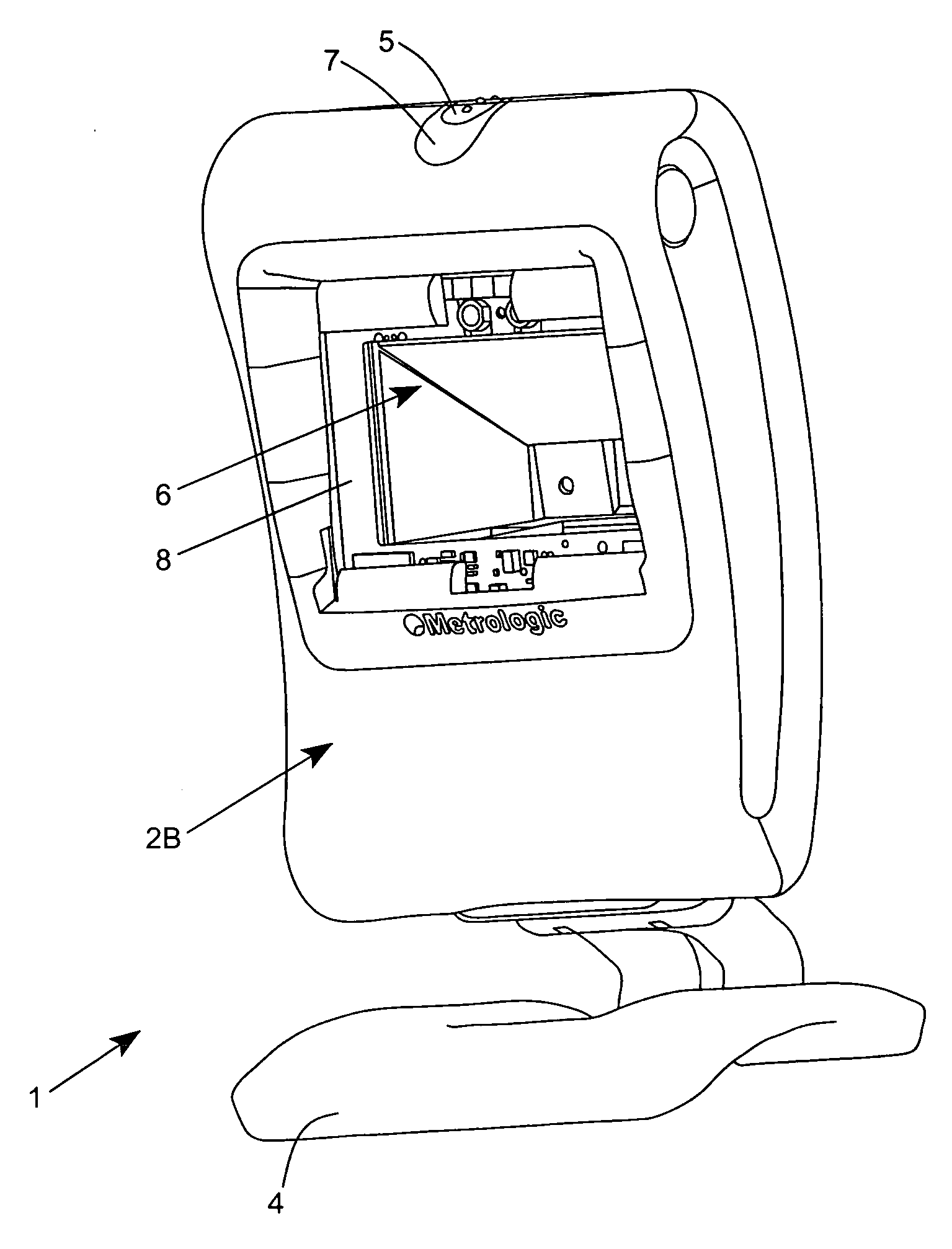
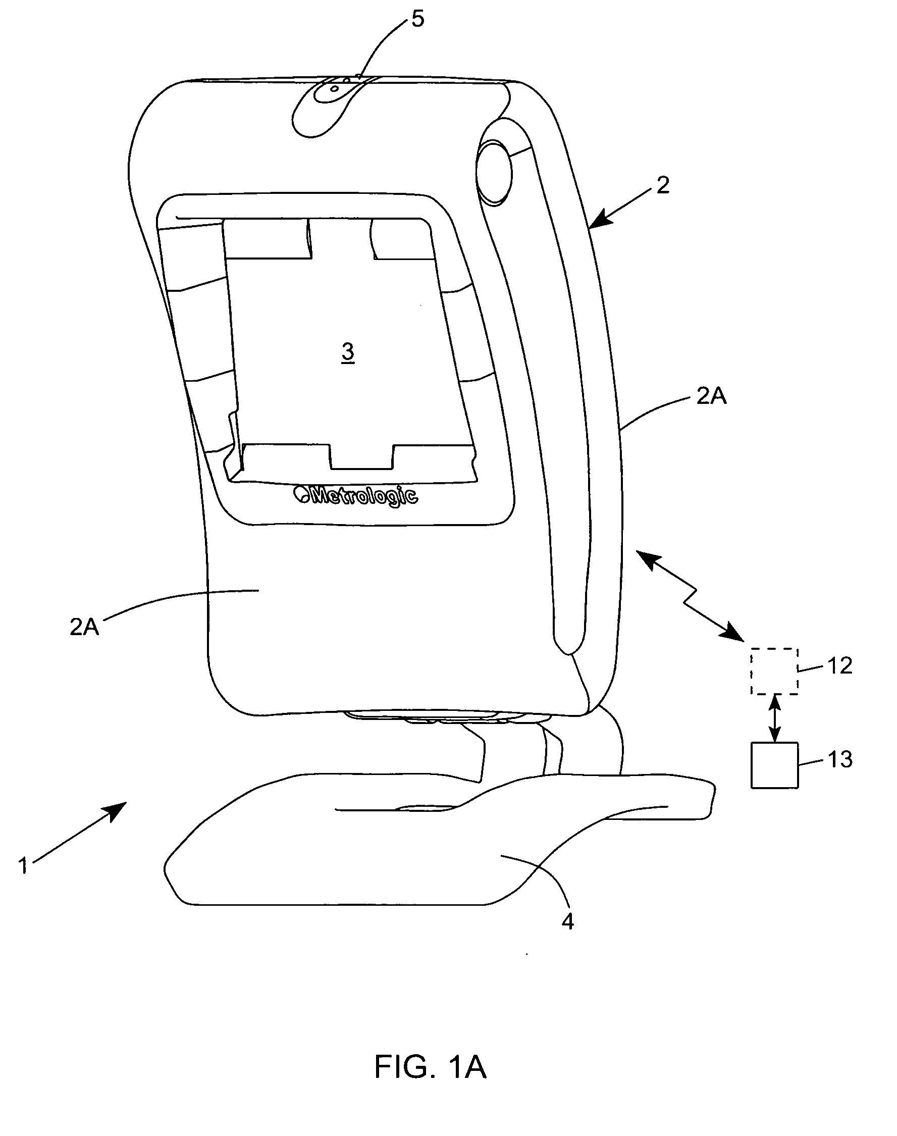
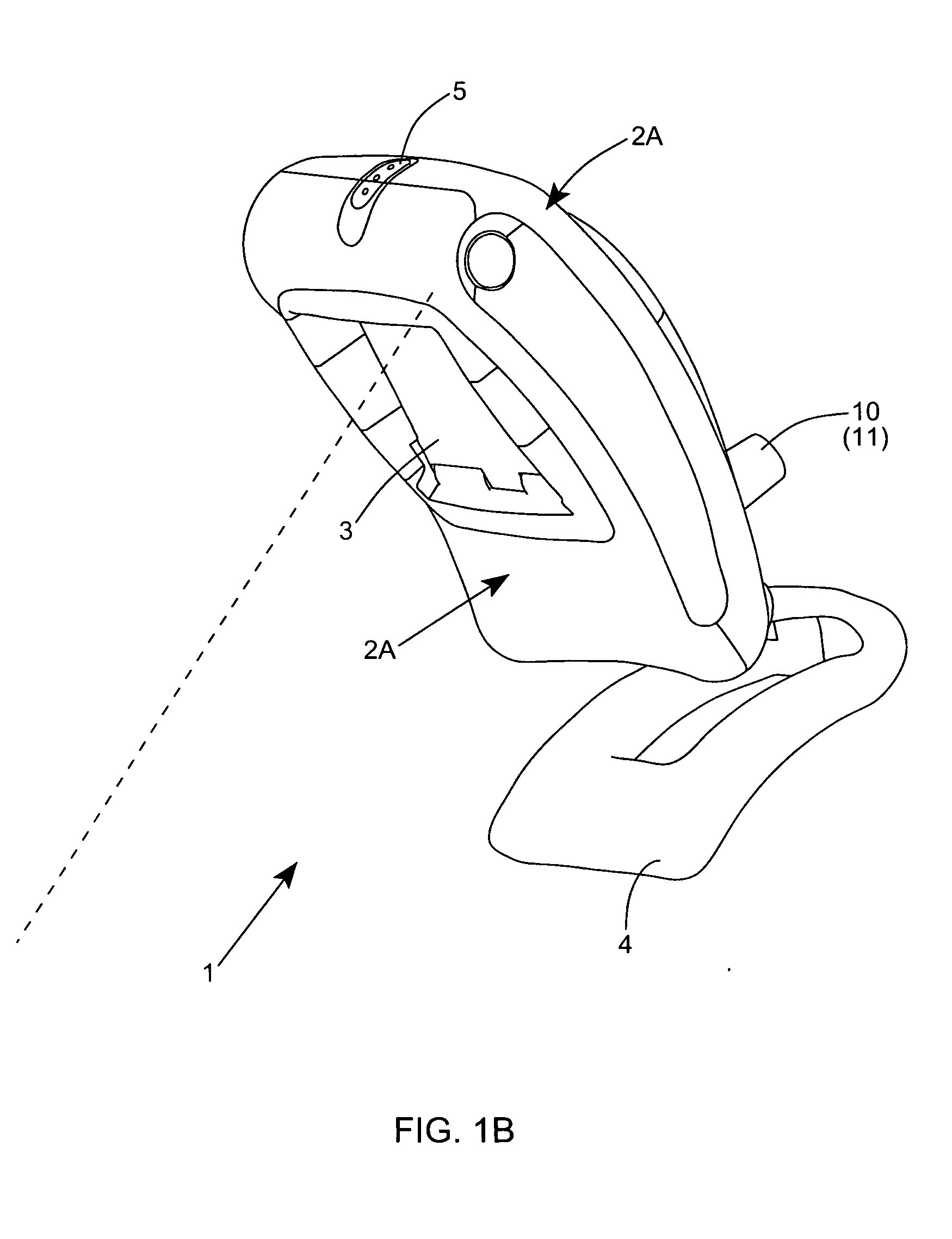
[0284]Referring to FIGS. 1A through 1F, the hand-supportable / countertop-supportable digital image capture and processing system of the first illustrative embodiment of the present invention 1 is shown in detail comprising a hand-supportable and countertop-supportable housing 2 having a rear housing portion 2a and a front housing portion 2B that is provided with a light transmission (i.e. imaging) window 3. As best shown, digital image capture and processing system further comprises: a foot-like structure 4 mounted to the r...


PUM


Abstract

A digital image capture and processing system including a housing having an imaging window; and an image formation and detection subsystem supporting a periodic snap shot mode of the operation. The system includes image formation optics for projecting a field of view (FOV) through said imaging window and upon an object within the FOV, and forming an image of the object on an area-type image detection array having a plurality of rows of image detection elements, and detecting 2D digital images of the object while object illumination and imaging operations. The system also includes an LED-based illumination subsystem, with a LED illumination array, for producing a field of narrow-band illumination within the FOV, and illuminating the object detected in the FOV, so that the illumination reflects off the object and is transmitted back through the light transmission aperture and onto the image detection array to form the 2D digital image of the object. During the periodic snap shot mode of the operation, the image detection array supports periodic image acquisition cycles, and during each image acquisition cycle, substantially all image detection elements in the image detection array are exposed simultaneously to the illumination. In the illustrative embodiment, each image acquisition cycle has a predetermined time duration followed by a decode-processing cycle having a time duration approximately equal to the duration of the image acquisition cycle so that at least ten (10) image frames can be acquired per second.

Description

RELATED CASES[0001]This application is a Continuation of U.S. application Ser. No. 12 / 001,758 filed Dec. 12, 2007; which is a Continuation-in-Part of the following U.S. application Ser. Nos. 11 / 640,814 filed Dec. 18, 2006; 11 / 880,087 filed Jul. 19, 2007; 11 / 305,895 filed Dec. 16, 2005; 10 / 989,220 filed Nov. 15, 2004; 10 / 712,787 filed Nov. 11, 2003; 10 / 893,800 filed Jul. 16, 2004; 10 / 893,797 filed Jul. 16, 2004; 10 / 893,798 filed Jul. 16, 2004; 10 / 894,476 filed Jul. 16, 2004; 10 / 894,478 filed Jul. 19, 2004; 10 / 894,412 filed Jul. 19, 2004; 10 / 894,477 filed Jul. 19, 2004; 10 / 895,271 filed Jul. 20, 2004; 10 / 895,811 filed Jul. 20, 2004; 10 / 897,390 filed Jul. 22, 2004; 10 / 897,389 filed Jul. 22, 2004; 10 / 901,463 filed Jul. 27, 2004; 10 / 901,426 filed Jul. 27, 2004; 10 / 901,446 filed Jul. 27, 2004; 10 / 901,461 filed Jul. 28, 2004; 10 / 901,429 filed Jul. 28, 2004; 10 / 901,427 filed Jul. 28, 2004; 10 / 901,445 filed Jul. 28, 2004; 10 / 901,428 filed Jul. 28, 2004; 10 / 902,709 filed Jul. 29, 2004; 10 / 901...

Claims


Application Information

Patent Timeline
Patent Type & Authority Applications(United States)
IPC IPC(8): G06K7/10
CPCG06K7/10722G06K7/10732G06K7/10821G06K7/109G06K7/10752
Inventor KOTLARSKY, ANATOLYZHU, XIAOXUNVEKSLAND, MICHAELAU, KA MANGIORDANO, PATRICKYAN, WEIZHENREN, JIESMITH, TAYLORMIRAGLIA, MICHAELKNOWLES, C. HARRYMANDAL, SUDHINFONEY, SHAWN DEALLEN, CHRISTOPHERWILZ, SR., DAVID M.
Owner METROLOGIC INSTR
Why Eureka
Try Eureka