Rotary clicking electronic component

a technology of electronic components and rotary clicks, applied in the direction of dashboard fitting arrangements, contact mechanisms, gearing, etc., can solve the problem of difficulty in creating rhythmical clicking sounds, and achieve the effect of enhancing the electrical reliability of the switch capable of obtaining clear rhythmical clicking sounds

Inactive Publication Date: 2008-11-27
PANASONIC CORP
View PDF11 Cites 13 Cited by
  • Summary
  • Abstract
  • Description
  • Claims
  • Application Information

AI Technical Summary

Benefits of technology

[0021]The present invention is intended to solve such a conventional problem, and the object of the invention is to provide a rotary clicking electronic component capable of obtaining smooth clicking and rhythmical clicking sound for a long period of time even in case of repeating the rotating operation.

Problems solved by technology

Also, the conventional clicking mechanism using plate spring 14 made of metal and rotary body 9 made of insulating resin involves such a problem that it is difficult to create a rhythmical clicking sound.

Method used


Image

  • Rotary clicking electronic component
  • Rotary clicking electronic component
  • Rotary clicking electronic component

Examples


Embodiment Construction

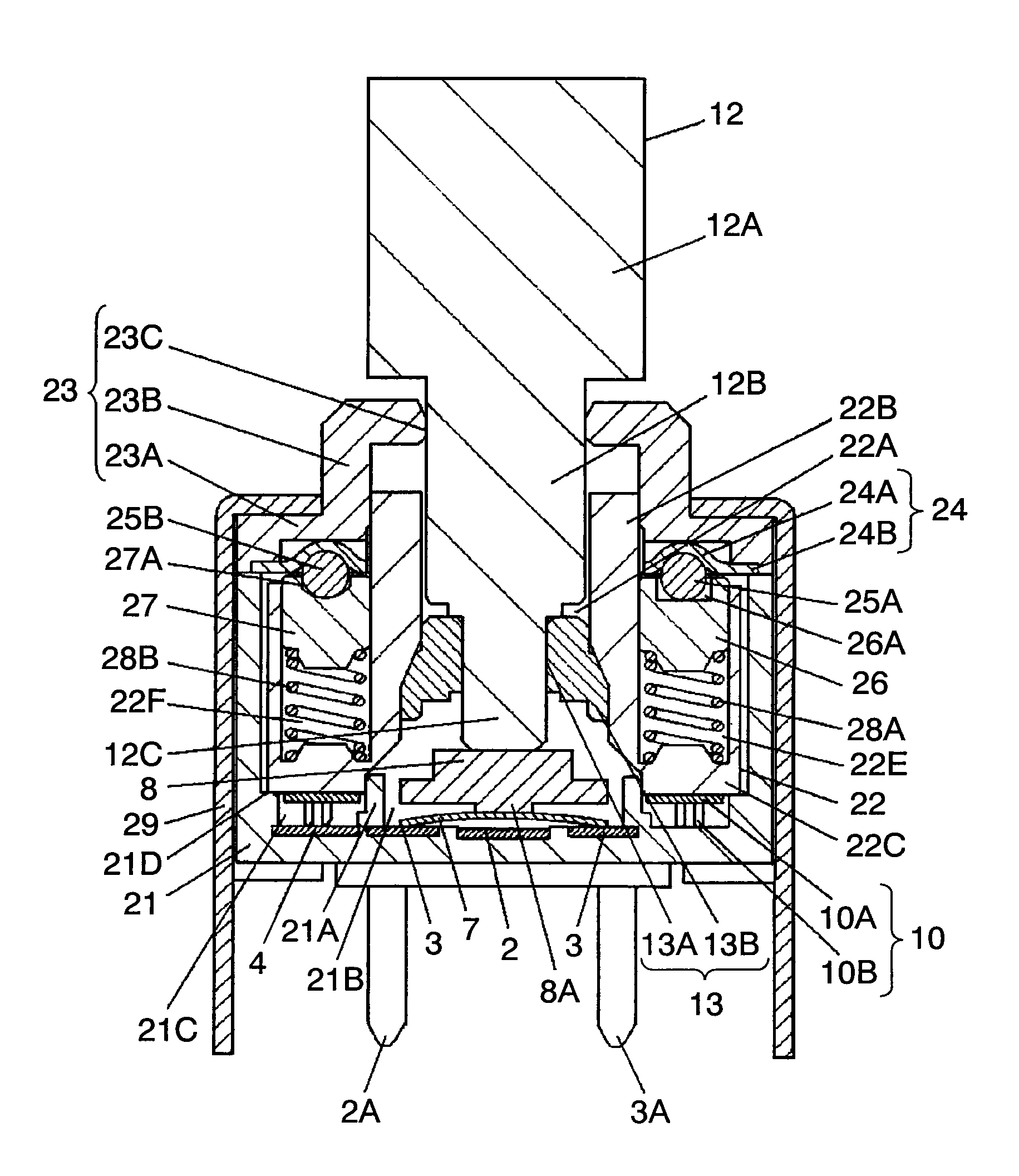
[0053]The rotary clicking electronic component in the exemplary embodiment of the present invention will be described in the following with reference to the drawings. The same components as in the conventional configuration are given same reference numerals, and the detailed description is omitted.

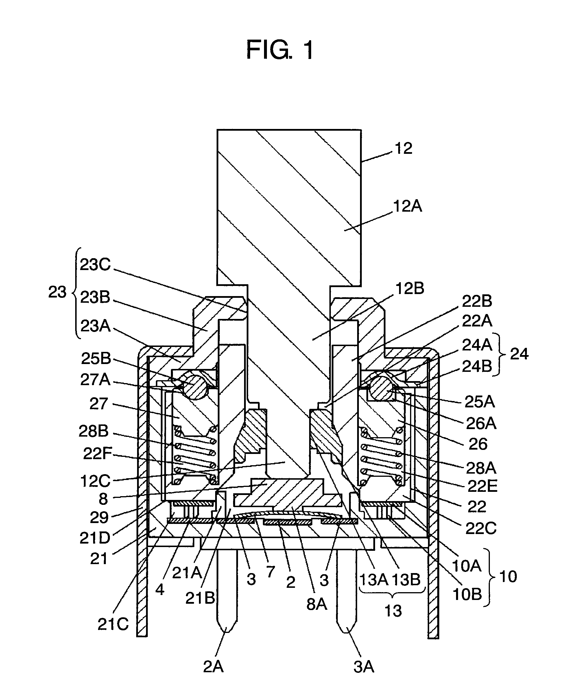
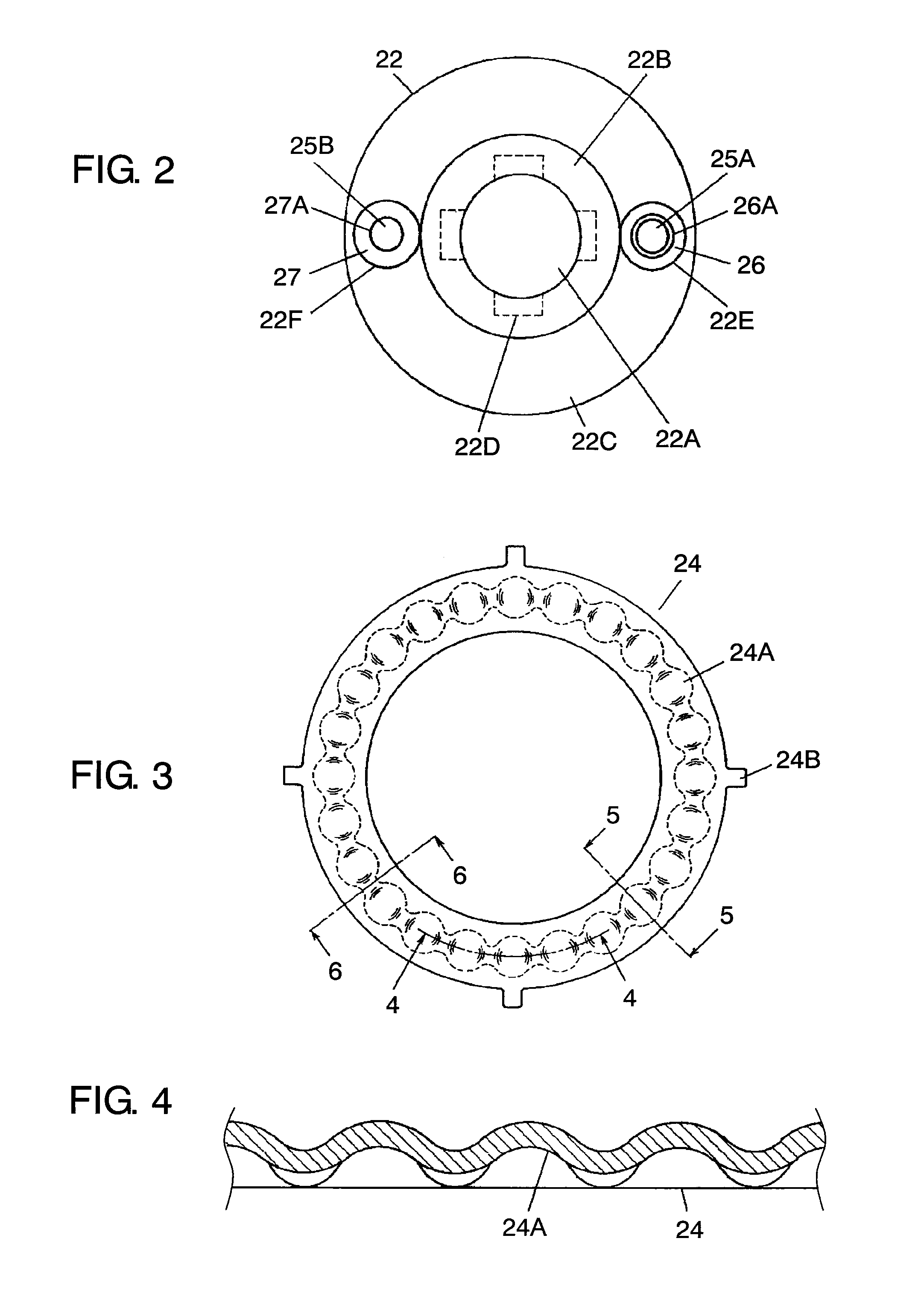
[0054]FIG. 1 is a sectional view of a rotary clicking composite switch as a rotary clicking electronic component in one exemplary embodiment of the present invention. FIG. 2 is a top view of a rotary body equipped with clicking members. FIG. 3 is a top view of a click plate thereof. FIG. 4 is a sectional view along the line 4-4 in FIG. 3. FIG. 5 is a sectional view along the line 5-5 in FIG. 3. FIG. 6 is a sectional view along the line 6-6 in FIG. 3. FIG. 7 and FIG. 8 are partially enlarged views of a clicking mechanism thereof. FIG. 9 to FIG. 11 are explanatory diagrams for describing the operation of the clicking mechanism.

[0055]In the figure, the opening of case 21 made of insulating re...


PUM


Abstract

Rotary body 22 is provided with storing hole 22E, 22F in two positions point-symmetrical to the rotational center at the upper part of flange 22C, and retainers 26, 27 having steel balls 25A, 25B, steel ball receiving holes 26A, 27A, coil springs 28A, 28B are stored therein from the opening side in order, and steel ball receiving hole 26A of one retainer 26 is provided with a tolerance that enables steel ball 25A to slightly move in the horizontal direction, and click plate 24 on which steel balls 25A, 25B are resiliently contacted is disposed between rotary body 22 and bearing 23, and as a result, it is possible to maintain rhythmical clicking and clicking sound even in case of repeating the rotating operation.

Description

BACKGROUND OF THE INVENTION[0001]1. Field of the Invention[0002]The present invention relates to a rotary clicking electronic component used in rotating sections of various electronic equipment.[0003]2. Background Art[0004]A rotary clicking electronic component provided with a clicking function that makes it easy to sense the amount of rotational operation is widely employed as a rotary electronic component used for setting the conditions or adjusting the output of various electronic equipment.[0005]As a conventional rotary clicking electronic component disclosed in Unexamined Japanese Patent Publication No. 2006-79966 and Unexamined Japanese Patent Publication No. 2005-302354, a rotary clicking composite switch will be described with reference to FIG. 12 to FIG. 19.[0006]FIG. 12 is a sectional view of a conventional rotary clicking composite switch. FIG. 13 is a top view of the case thereof. FIG. 14 is a top view of the rotary body thereof. FIG. 15 is a top view of the slide thereo...

Claims


Application Information

Patent Timeline
Patent Type & Authority Applications(United States)
IPC IPC(8): F16H35/18
CPCB60K37/06B60K2350/102H01H19/11H01H25/06B60K2370/126
Inventor MIURA, SEIKINISHIMOTO, TAKUMI
Owner PANASONIC CORP
Why Eureka
Try Eureka