
Method for utilizing time domain method to make difference measurement of accurate reconfiguration

A differential measurement and accurate technology, applied in the field of detection applications, can solve the problems of influence, high cost, and low practicability, and achieve the effect of improving detection efficiency and reducing costs

Inactive Publication Date: 2004-02-25
NAT UNIV OF DEFENSE TECH
View PDF0 Cites 10 Cited by
  • Summary
  • Abstract
  • Description
  • Claims
  • Application Information

AI Technical Summary

Problems solved by technology

The currently proposed method of measuring the straightness of a cylinder with a multi-probe system uses two groups of six probes, and also uses the principle of the three-point method for measurement. In order to avoid the influence of zero-adjustment errors, this method requires two measurements by flipping the workpiece , so expensive and impractical
[0007] It can be seen from the above that people are doing more and more in-depth research on the straightness measurement method, especially its algorithm, in order to reconstruct the straightness profile of the workpiece at sufficiently small sampling interval points with high precision, but now None of these algorithms can achieve this goal, that is, it is not possible to accurately reconstruct the straightness of any workpiece without theoretical error at each point at a sufficiently small sampling interval smaller than the sensor spacing
[0008] As for the transverse shearing interferometry, because of its simple and stable structure and the need for high-precision reference surfaces, it is widely used in the detection of high-precision optical surface shapes, especially the detection of free-form surfaces such as aspherical surfaces. Reconstruction based on difference is a very complicated problem. Over the past 20 years, people have developed a variety of calculation methods. The previous method was based on the reconstruction of adjacent point difference values. It was not until recent years that a large shearing method was proposed. Reconstruction methods, which have led to broader interest in the recent study of transverse shear interference, but all of these methods suffer from certain limitations, either assuming some "prior" knowledge of the wavefront being studied such as smoothness, etc. , or use a small shear amount equal to the measurement point interval to measure (the sensitivity of the detection will be affected at this time), or even only an approximate solution can be obtained

Method used


Image

  • Method for utilizing time domain method to make difference measurement of accurate reconfiguration
  • Method for utilizing time domain method to make difference measurement of accurate reconfiguration
  • Method for utilizing time domain method to make difference measurement of accurate reconfiguration

Examples


Embodiment Construction

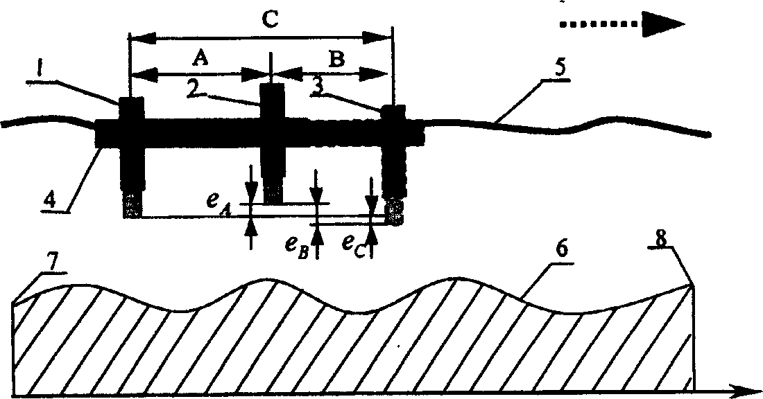
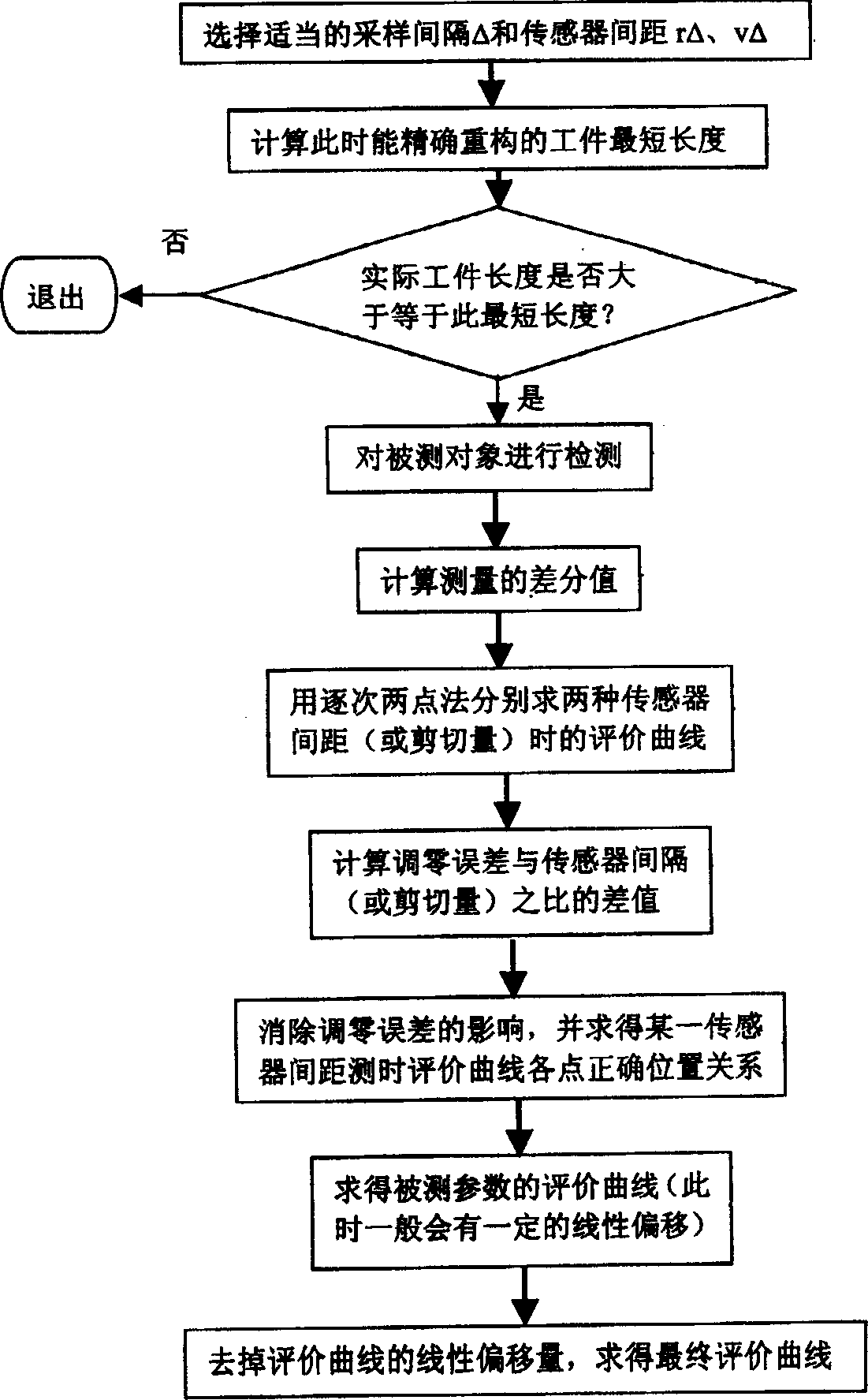
[0020] The invention accurately reconstructs the measured parameters through the time domain method according to the difference values ​​measured by two different distances or shearing amounts on the measured object. It firstly evaluates two groups of different differential values ​​with the successive two-point method, and the number of evaluation curves obtained by each group is the ratio of the corresponding sensor spacing or shear volume sampling interval, and then uses the difference between the two groups of curves Calculate the influence of the zero adjustment error on the evaluation results, find out the relationship between each curve in the two sets of curves, and finally combine these curves into an evaluation curve. This method itself can be applied to the general situation when the size of the measured piece is not an integer multiple of the product of the two sensor spacing or the shear amount, such as the sampling interval is not equal to the sensor spacing or th...


PUM


Abstract

The method for making accurate restructure of difference measurement by using time domain is characterized by that according to the difference value obtained by measuring two different separation distances or shearing quanties of measured object, respectively using successive two-point method to evaluate two groups of different difference values, the number of evaluation curves obtained by every group is the ratio value of correspondent sensor separation distance or shearing quantity and sampling interval, then utilizing the interrelationship between two groups of the curves to calculate the influence of zero modulation error to the evaluation result so as to resolve the interrelationship between every curves in the two groups of curves, finally synthesizing these curves into an evaluation curve.

Description

Technical field: [0001] The invention relates to the technical field of detection applications, in particular to a detection method for reconstructing the original measured parameters according to the differential measurement values ​​of the measured parameters, including the straightness, flatness, cylindricity, and free-form surface of precision and ultra-precision workpiece surfaces. Surface shape detection and wavefront reconstruction for transverse shear interference. Background technique [0002] In ultra-precision machining, in order to detect the straightness, cylindricity, flatness and surface accuracy of the surface of the workpiece, the multi-probe scanning method is often used. This method uses the displacement probe (commonly used non-contact sensors such as eddy current or Capacitance, etc.) or angle detectors (such as autocollimators, etc.) are installed on the slide plate and move linearly along the measured contour of the workpiece, or the sensor is fixed, a...

Claims


Application Information

Patent Timeline
Patent Type & Authority Applications(China)
IPC IPC(8): G01B7/28G01B11/26
Inventor 李圣怡尹自强戴一帆郑子文王宪平
Owner NAT UNIV OF DEFENSE TECH
Learn More