Power tool

Inactive Publication Date: 2009-01-15
DEMAIN TECH
View PDF30 Cites 27 Cited by
  • Summary
  • Abstract
  • Description
  • Claims
  • Application Information

AI Technical Summary

Benefits of technology

[0012]Preferably, when the power tool is in the adjustment mode and the drive means rotates in a direction for gripping the working element the torque control means renders the drive means inoperable at a relatively lower torque level and when the drive means rotates in a direction for releasing the working element the torque control means renders the drive means inoperable at a relatively higher torque level. An advantage of this embodiment is that it may provide that a greater amount of torque is applied for releasing the working element than for gripping the working element and thus may provide that the chuck jaws will release the working element and not become jammed.
[0013]Preferably, the torque control means includes a geared slip ring having an annular surface with spaced apart casselations defining cups therebetween, each casselation having two surfaces inclined to a substantially different degree relative to the annular surface of the geared slip ring for when the drive means rotates in the direction for gripping the working element the less inclined casselation surface engages a compression means and provides for a relatively less amount of torque required to overcome a given compressional force applied by the compression means to render the drive means inoperable and for when the drive means rotates in the direction for releasing the working element the more inclined casselation surface engages the compression means and provides for a relatively greater amount of torque required to overcome a given compressional force applied by the compression means to render the drive means inoperable.

Problems solved by technology

However, the applicant has appreciated that if too much force is applied to the jaws it may damage or even crush the working element or break the jaws.

Method used


Image

  • Power tool
  • Power tool
  • Power tool

Examples


Embodiment Construction

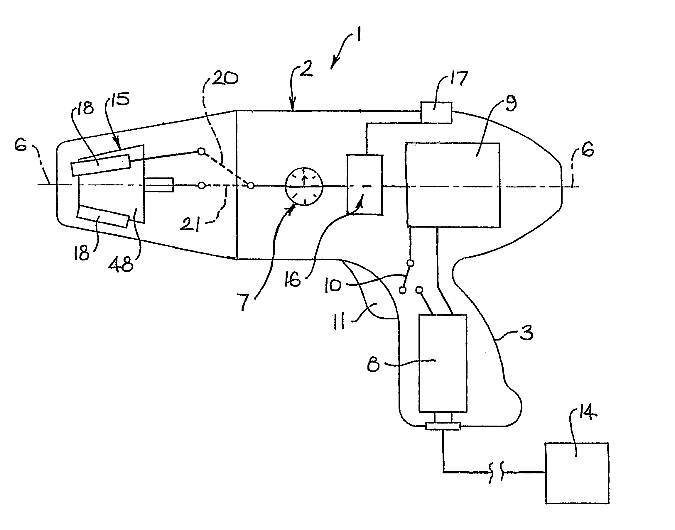
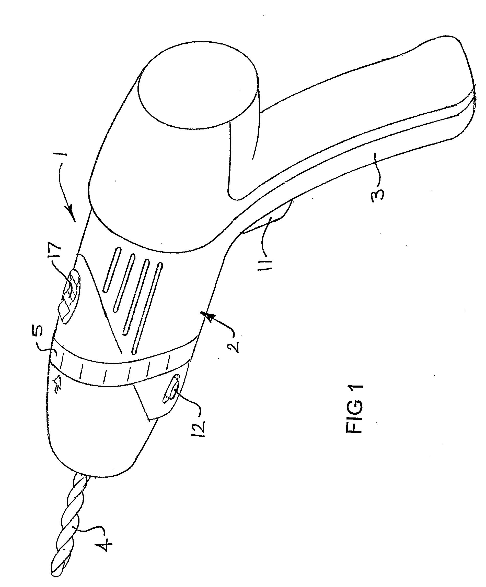
[0029]FIG. 1 of the drawings shows one form of portable power drill 1 to which the invention is applicable, but as previously stated the invention is applicable to other types of power tools including non-portable power tools. The drill shown in FIG. 1 incorporates an example embodiment of the invention. The drill, as shown in FIG. 1, includes a body 2 having a pistol grip 3 at the back end thereof. A working element 4 is illustrated extending from a front end of the drill 1. The drill 1 includes numerous features which are best described with reference to illustrations of the inner workings of the tool. These features are actuated by elements on the exterior of the power tool and whilst they will be described in detail later in the specification, FIG. 1 illustrates a trigger 11 on the pistol grip 3, a mode selector 17, a torque setting selector 5 and a directional switch 12.

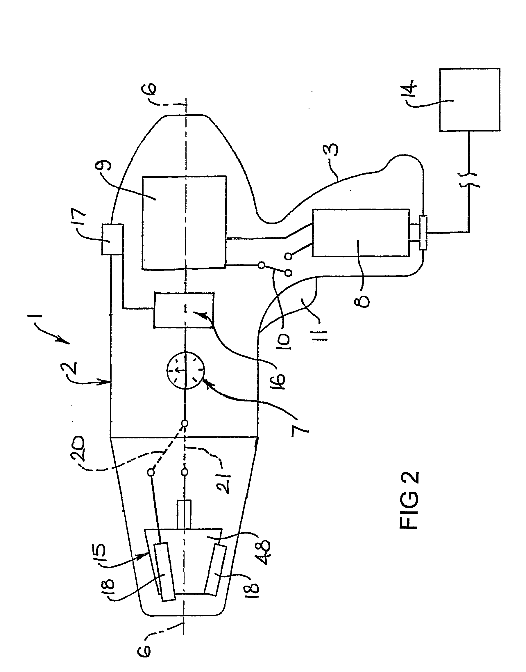
[0030]FIG. 2 is a diagrammatic illustration of one particular arrangement of the drill 1. In the arrangement ...


PUM

PropertyMeasurementUnit
Forceaaaaaaaaaa
Speedaaaaaaaaaa
Torqueaaaaaaaaaa

Abstract

A power (1) tool including a driven member (15) that is operable to grip and drive at least one working element (4), drive means (25) operable to drive the driven member, the power tool being operable in either a working mode in which the driven member is driven to enable the working element to perform work, or an adjustment mode in which the driven member is adjusted to grip or release the working element, torque control means (7) controlling the torque produced by the drive means, the torque control means being operable to render the drive means inoperable when the torque exceeds a pre-determined level, the torque control means having an adjustment setting (17) which must be selected to enable the power tool to operate in an adjustment mode whereby the adjustment setting corresponds to a relatively low level of torque.

Description

FIELD OF THE INVENTION[0001]This invention relates to power tools of the kind having a drive means driving a driven member which is adapted to releasably hold a working element. More specifically, the power tool is operable in a working mode to drive the working element and in an adjustment mode to grip or release the working element. A power drill is one form of power tool to which the invention is applicable and it will be convenient to hereinafter describe the invention with particular reference to power drills. It should be appreciated however that the invention has wider application being applicable to any power tool in which the working element is used to cut, shape or otherwise treat a workpiece or fastener associated with a workpiece.BACKGROUND OF THE INVENTION[0002]Conventional power drills typically have a driven member including a three jaw chuck which grips a working element such as a drill bit or screw driver head or the like. The chuck jaws are adjustable, normally by ...

Claims


Application Information

Patent Timeline
IPC IPC(8): B23B45/02
CPCB23B31/123B23B45/008B23B45/02Y10T408/70B23B2260/0445B25F5/001B23B2231/06
Inventor SCRIMSHAW, DAVID LEIGHVAN DER LINDE, BENJAMIN LUKECONNOR, PAUL FRANCIS
Owner DEMAIN TECH
Why Eureka
Try Eureka