
Electric machine comprising a rotor and a stator

a technology of electric machines and stators, which is applied in the direction of dynamo-electric machines, magnetic circuit rotating parts, magnetic circuit shapes/forms/construction, etc., can solve the problems of low torque ripple, low loss, and high level of rotor flux with a low level of torque ripple at the same time low, so as to achieve high torque, high performance level, and high level of rotor flux

Active Publication Date: 2019-08-01
ROBERT BOSCH GMBH
View PDF5 Cites 9 Cited by
  • Summary
  • Abstract
  • Description
  • Claims
  • Application Information

AI Technical Summary

Benefits of technology

The invention is about an electric machine with high torque and performance, low noise, low losses, and good demagnetization capability. The machine has a specific arrangement of magnet pockets that results in high rotor flux and low torque ripple. The magnet pockets of the second pair are spaced apart from each other, and their smallest distance is larger than the magnet pockets of the first pair, which increases the speed performance. The magnet pockets of the second pair are arranged with an electrical pole-pitch angle of approximately 190° to approximately 200°, which reduces torque ripple and noise. The magnet pockets of the first pair have a smaller height, which improves demagnetization stability and low costs. Overall, this design provides a compact electric machine with excellent performance.

Problems solved by technology

At the same time, the electric machine has a low level of torque ripple and thus also gives rise to a low level of noise.
Precise investigations of a computer-based “multi-objective optimization” have shown that the double-V arrangement of magnet pockets at certain angles results in a high level of rotor flux with a simultaneously low level of torque ripple and low losses.

Method used


Image

  • Electric machine comprising a rotor and a stator

Examples


Embodiment Construction

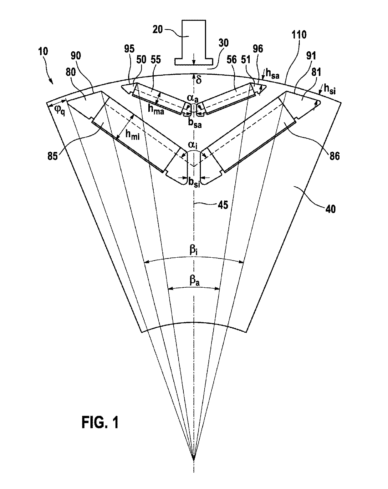
[0023]FIG. 1 shows a schematic view of a region of one embodiment of the electric machine according to the invention. The electric machine comprises a rotor 10 and a stator 20. The electric machine can be, in particular, a permanently energized synchronous machine. The electric machine can be used in hybrid and electric vehicles.

[0024]An air gap 30 (δ) is present between the rotor 10 and stator 20. The air gap 30 between the rotor 10 and the stator 20 is approximately 1.0 mm to approximately 2 mm, in particular approximately 1.0 mm to approximately 1.7 mm.

[0025]FIG. 1 illustrates a pole segment 40 of the rotor 10. The rotor 10 comprises a plurality of similarly or identically constructed pole segments 40 along its circumferential direction. The pole segment 40 has two pairs 50, 51, 80, 81 of magnet pockets. A first pair of magnet pockets 50, 51, i.e. two magnet pockets 50, 51 which belong to one another, are arranged further toward the outside in the radial direction of the rotor 10...


PUM


Abstract

The invention relates to an electric machine comprising a rotor (10) and a stator (20). The rotor (10) has magnet pockets for receiving permanent magnets (55, 56, 85, 86), and the magnet pockets comprise at least one first pair of magnet pockets (50, 51) and a second pair of magnet pockets (80, 11). The second pair (80, 81) is arranged further inwards than the first pair (50, 51) when viewed in a radial direction with respect to a rotational axis, and the magnet pockets of each pair of magnet pockets (50, 51, 80, 81) are arranged symmetrically to one another with respect to an axis of symmetry (45), wherein the axis of symmetry (45) runs in the radial direction and through the center of the rotor (10). The magnet pockets of each pair of magnet pockets (50, 51, 80, 81) are arranged such that the distance of each magnet pocket to the axis of symmetry (45) increases as the distance to the circumferential edge (110) of the rotor (10) decreases. The magnet pockets of the first pair (50, 51) are arranged at a first mechanical angle to one another, and the magnet pockets of the second pair (80, 81) are arranged at a second mechanical angle to one another. The invention is characterized in that the first angle ranges from ca. 100° to ca. 140°, in particular from ca. 120° to ca. 140°, and the second angle ranges from ca. 65° to ca. 112°, in particular from ca. 88° to ca. 112°.

Description

BACKGROUND OF THE INVENTION[0001]The invention relates to an electric machine comprising a rotor and a stator.[0002]A large number of electric machines having a rotor and a stator are known. It is in particular the magnetic rotor flux which is to be taken into account in electric machines. The aim is to achieve a high level of rotor flux.[0003]U.S. Pat. No. 8,994,240 B describes an electric machine in which two pairs of magnet pockets for accommodating magnets are provided in a respectively V-shaped arrangement. The objective here is to achieve a maximum level of rotor flux.[0004]The disadvantage here, however, is that such an electric machine usually has a high level of torque ripple. It is also the case with previously known electric machines that the increased level of rotor flux usually results in an increase in the losses. It is generally the case that high losses are generated in particular in the field-weakening range.SUMMARY OF THE INVENTION[0005]Embodiments of the present i...

Claims


Application Information

Patent Timeline
Patent Type & Authority Applications(United States)
IPC IPC(8): H02K1/27
CPCH02K1/276H02K2201/06H02K29/03H02K1/2766H02K2213/03
Inventor KOL, MURATHEUSER, PATRICK
Owner ROBERT BOSCH GMBH
Learn More