Process for Making Swaged Lighting Holes in Planar Areas of Preimpregnated Composite Parts

US20090020217A1Active Publication Date: 2009-01-22AIRBUS OPERATIONS SL

Image

  • Process for Making Swaged Lighting Holes in Planar Areas of Preimpregnated Composite Parts
  • Process for Making Swaged Lighting Holes in Planar Areas of Preimpregnated Composite Parts
  • Process for Making Swaged Lighting Holes in Planar Areas of Preimpregnated Composite Parts

Examples


Embodiment Construction

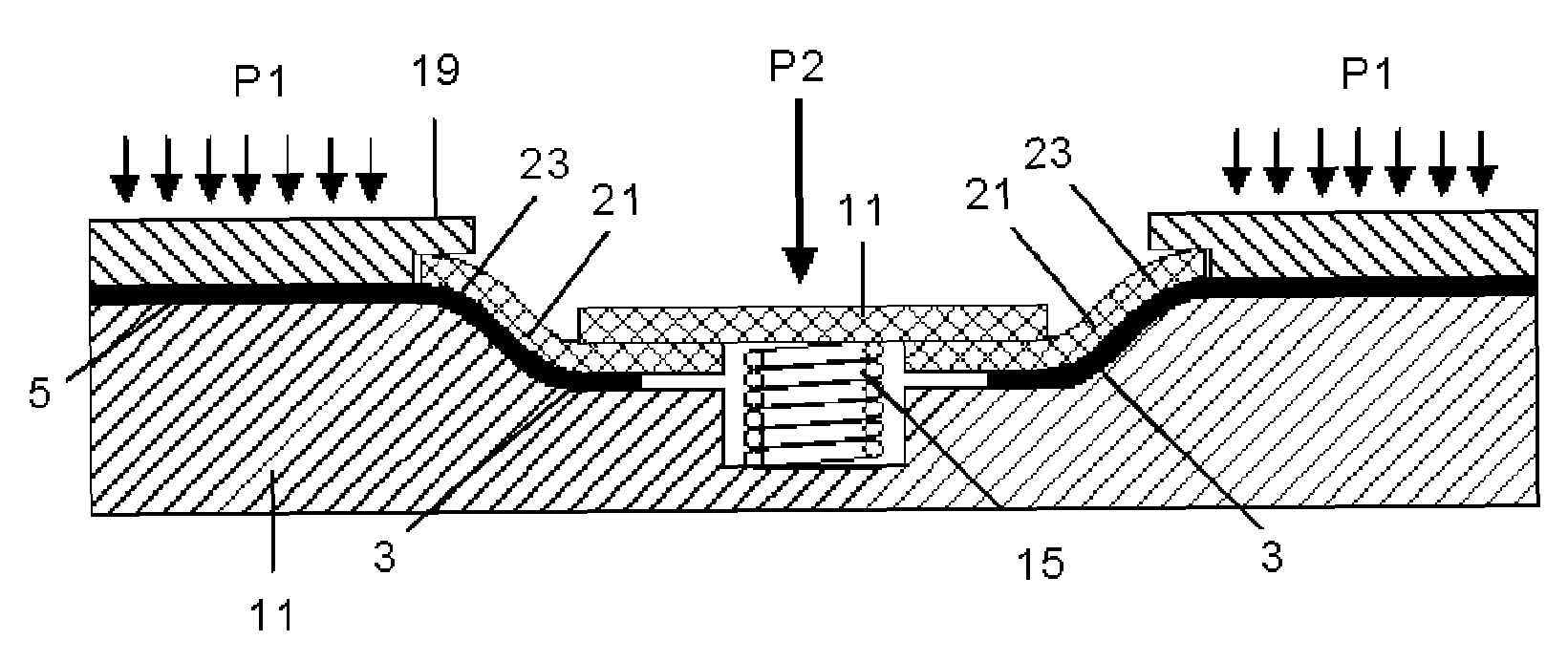
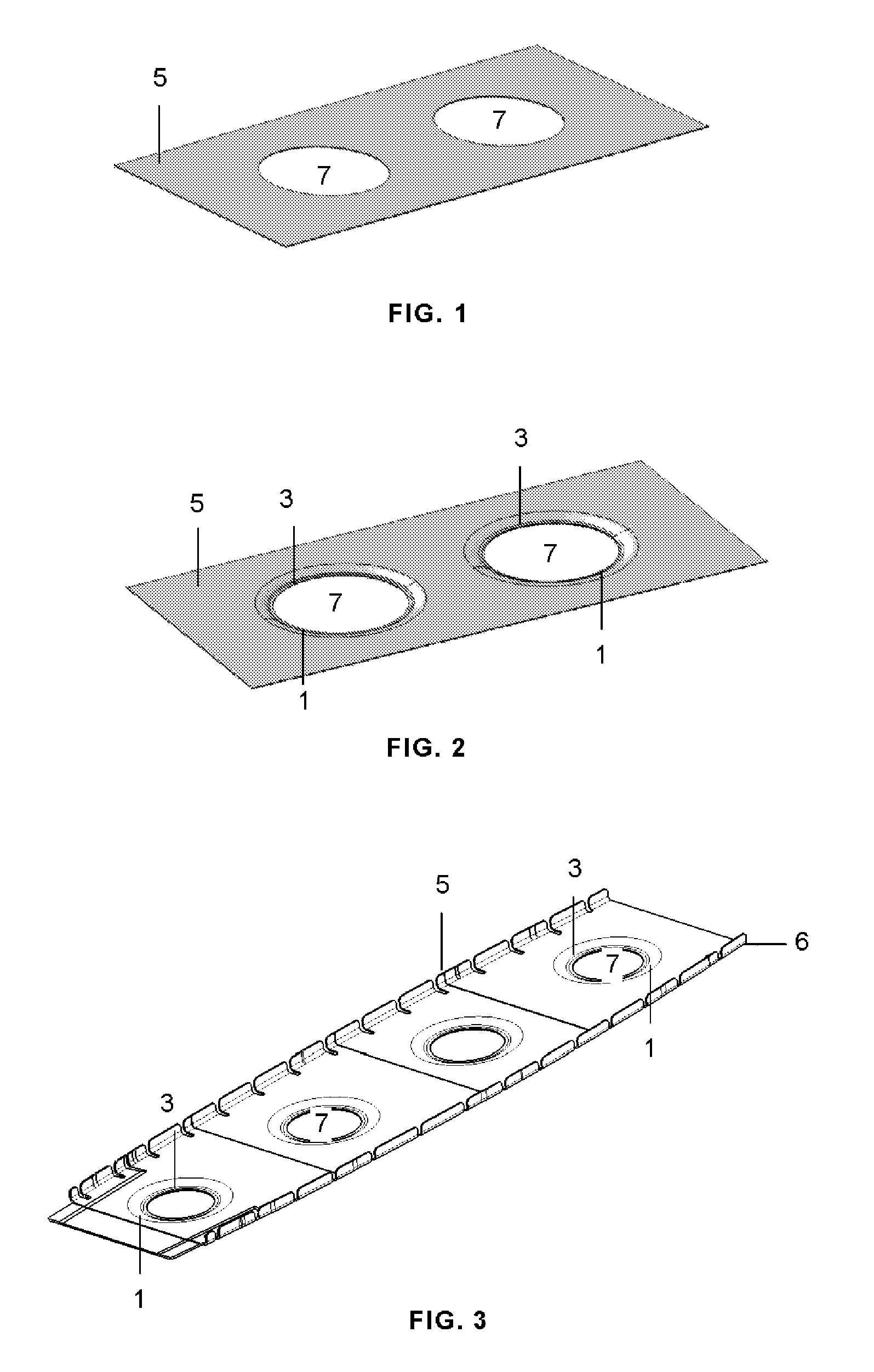
[0018]An embodiment of the process according to the invention for carrying out the swaged lighting hole 1 consisting, as is shown in the cases represented in FIGS. 2 and 3, of a recess of an area 3 of the part 5 surrounding the opening 7, with an S-shaped contour, is described below. As the person skilled in the art will understand, the swaged lighting hole may have another shape.

[0019]The swaged lighting holes 3 are made in a planar or quasi-planar area of the part 5, but the latter may have a non-planar shape like the part 5 shown in FIG. 3, which corresponds to a rib with a C-shaped section, in which the flanges 6 have been formed prior to making the swaging according to this invention.

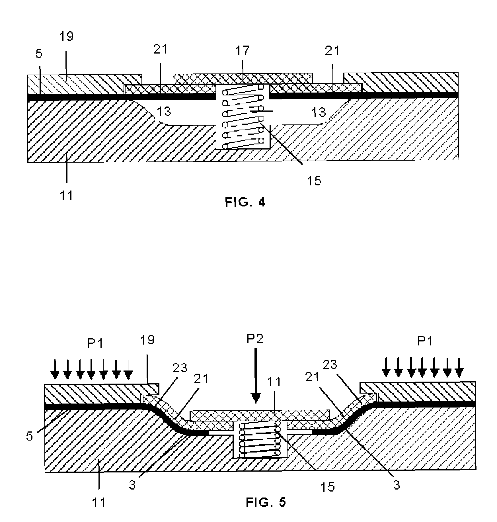
[0020]The part 5 is covered with a thin plastic film (not represented) to prevent it from adhering to the tooling of the swaged lighting hole process and is placed, suitably centering it, on a female tooling 11 the top side of which reproduces the shape that the part must be given during the swagin...


PUM

PropertyMeasurementUnit
Temperatureaaaaaaaaaa
Pressureaaaaaaaaaa
Areaaaaaaaaaaa

Abstract

The invention relates to a process for making swaged lighting holes (1) in planar areas of parts (5) made of preimpregnated composite, by means of which the part (5) is arranged between a female tooling (11) with the final shape of the bottom side of the swaged part and a caul plate (19) with the final shape of the top side of the swaged part, except in an area (3) which must be swaged, pressure P1 is applied on the caul plate (19) in the area of the part (5) that must be maintained substantially planar, and pressure P2 is applied by means of a male tooling (17) on the area (3) of the part (5) which must be swaged at a forward speed allowing the flow of the resin during the slippage of the fibers of the material so that it may deform, adapting to the final shape of the female tooling (11).

Description

FIELD OF THE INVENTION[0001]This invention relates to a process for making swaged lighting holes in planar areas of preimpregnated composite parts, and particularly in parts made by means of automatic laying machines.BACKGROUND OF THE INVENTION[0002]The use of swaged lighting holes in structural parts is common in order to achieve an increase of stiffness without increasing the weight and with a minimum cost.[0003]The processes for making swaged lighting holes on sheet metal are common in industry and achieve the desired deformation of the sheet by means of its plastic deformation.[0004]In the case of composite parts formed with stiff continuous fibers, however the mechanism allowing the adaptation to the desired shape of the swaged lighting hole is based on the relative slippage of fibers.[0005]In parts made with composites, the traditional process for making swaged lighting holes consists of manually laminating each layer, adapting it to the geometry of the swaged lighting hole. T...

Claims


Application Information

Patent Timeline
22 Jan 2009
Publication
US20090020217A1
IPC
B44C3/08
CPC
B29C51/12; B29C70/342; Y10T156/1039; B29C70/545; B29C70/541; B29C70/549
Inventors
CANO CEDIEL, DAVID; MENENDEZ MARTIN, JOSE MANUEL