Lubrication device for belt-driven continuously variable transmission

a technology of lubrication device and continuously variable transmission, which is applied in the direction of belt/chain/gearing, gear lubrication/cooling, belt/chain/gearing, etc., can solve the problems of increasing the slippage between the belt and the pulley, suppressing the vibration of the belt, and increasing the slippage

Active Publication Date: 2018-02-06
TOYOTA JIDOSHA KK
View PDF20 Cites 0 Cited by
  • Summary
  • Abstract
  • Description
  • Claims
  • Application Information

AI Technical Summary

Benefits of technology

[0012]The lubrication device is further provided with a controller that controls a discharge amount of the oil from the opening. Specifically, the belt is a chain belt comprising a plurality of oval plate links arranged alternately to one another in a circular manner, and a plurality of pins individually inserted into each pin hole of the link to connect the adjoining links while allowing to pivot therearound. Specifically, the controller may be configured to reduce the discharge amount of the oil from the opening with an increase in a slippage between the belt and the pulley.
[0013]The lubrication device is further provided with an oil passage connected to the opening, and the controller may be further configured to reduce an oil delivery amount to the oil passage with an increase in a slippage between the belt and the pulley.
[0017]The stabilizer is further provided with a pair of plate members being opposed to each other individually brought into contact to the belt running therebetween to suppress vibrations of the belt.
[0018]Thus, the stabilizer according to the preferred example is brought into contact to the straight portion of the belt between the pulleys to suppress vibrations of the belt. In addition, the opening of the stabilizer is oriented to the contact point between the belt and the pulley while being allowed to pivot and twist in response to a change in posture of the belt resulting from a speed change operation. According to the preferred example, therefore, the opening can be kept to be oriented to the contact point between the belt and the pulley to apply oil thereto even if the contact point is displaced as a result of the speed change operation. For this reason, the contact point between the belt and the pulley can be lubricated sufficiently irrespective of the current speed ratio.
[0019]In addition, an oil delivery amount to the contact point between the belt and the pulley can be reduced with an increase in a slippage between the belt and the pulley. According to the preferred example, therefore, oil will not be applied excessively to the contact point so that slippage of belt in the pulley can be avoided to improve transmitting efficiency of the continuously variable transmission.

Problems solved by technology

Specifically, the controller may be configured to reduce the discharge amount of the oil from the opening with an increase in a slippage between the belt and the pulley.

Method used


Image

  • Lubrication device for belt-driven continuously variable transmission
  • Lubrication device for belt-driven continuously variable transmission
  • Lubrication device for belt-driven continuously variable transmission

Examples


Embodiment Construction

)

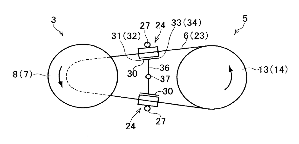
[0030]The belt-driven continuously variable transmission to which the lubrication device of the preferred example is applied comprises a pair of pulleys and a belt running between those pulleys. A structure of the belt-driven continuously variable transmission will be explained in more detail with reference to FIG. 8. As illustrated in FIG. 8, the belt-driven continuously variable transmission (to be abbreviated as the “CVT” hereinafter) 1 comprises an input shaft 2 to which a torque is delivered from a prime mover such as an engine, a primary pulley fitted onto the input shaft 2, an output shaft 4 that delivers a torque to an output member such a driving wheels, a secondary pulley 5 fitted onto the output shaft 5, and an endless belt 6 running between the pulleys 3 and 5. The input shaft 2 and the output shaft 4 are arranged parallel to each other.

[0031]The primary pulley 3 comprises a first fixed sheave 7 formed integrally with the input shaft 2, and a first movable sheave 8 fitt...


PUM


Abstract

A lubrication device for a belt-driven continuously variable transmission is provided. The lubrication device comprises a stabilizer 24 brought into contact to a straight portion of a belt 6 between the pulleys to suppress vibrations of the belt. The stabilizer 24 comprises openings 31, 32, 33 and 34 oriented to each contact point between a sheave 7, 8, 13 or 14 and the belt 6 to apply oil thereto, while being allowed to pivot and twist in response to a change in posture of the belt 6 resulting from a speed change operation to keep the opening oriented to the contact point.

Description

[0001]The present invention claims the benefit of Japanese Patent Applications No. 2015-004287 filed on Jan. 13, 2015 with the Japanese Patent Office, the disclosures of which are incorporated herein by reference in its entirety.BACKGROUND[0002]Field of the Invention[0003]The present invention relates to a belt-driven continuously variable transmission having a pair of pulleys and a belt running between the pulleys, and more particularly, to a lubrication device for lubricating a contact point between the pulley and the belt.[0004]Discussion of the Related Art[0005]JP-A-2014-5873 describes a lubrication device for continuously variable transmissions adapted to apply lubricant to an inner circumferential region of a conical face. According to the teachings of JP-A-2014-5873, the lubrication device is provided with a stabilizer adapted to suppress vibrations of the belt by a pair of plate members. The stabilizer is allowed to tilt around a support shaft in accordance with a speed rati...

Claims


Application Information

Patent Timeline
Patent Type & Authority Patents(United States)
IPC IPC(8): F16H57/04F16H9/18F16H7/18F16H9/24
CPCF16H57/0456F16H9/18F16H57/0489F16H9/24F16H7/18F16H9/12F16H57/028F16H57/0434
Inventor SHIBATA, NAOYUKI
Owner TOYOTA JIDOSHA KK
Why Eureka
Try Eureka