Airflow estimation method and apparatus for internal combustion engine

a technology for internal combustion engines and airflow estimation, which is applied in the direction of electrical control, process and machine control, instruments, etc., can solve the problems of inability to use speed density methods in conjunction with more complex engine applications such as cam-phasing and/or variable valve lift capability, and is not practical or economically feasibl

Active Publication Date: 2009-01-22
GM GLOBAL TECH OPERATIONS LLC
View PDF9 Cites 14 Cited by
  • Summary
  • Abstract
  • Description
  • Claims
  • Application Information

AI Technical Summary

Problems solved by technology

However, employing the speed-density methods in conjunction with more complex engine applications such as cam-phasing and / or variable valve lift capability has not been practical or economically feasible.

Method used


Image

  • Airflow estimation method and apparatus for internal combustion engine
  • Airflow estimation method and apparatus for internal combustion engine
  • Airflow estimation method and apparatus for internal combustion engine

Examples


Embodiment Construction

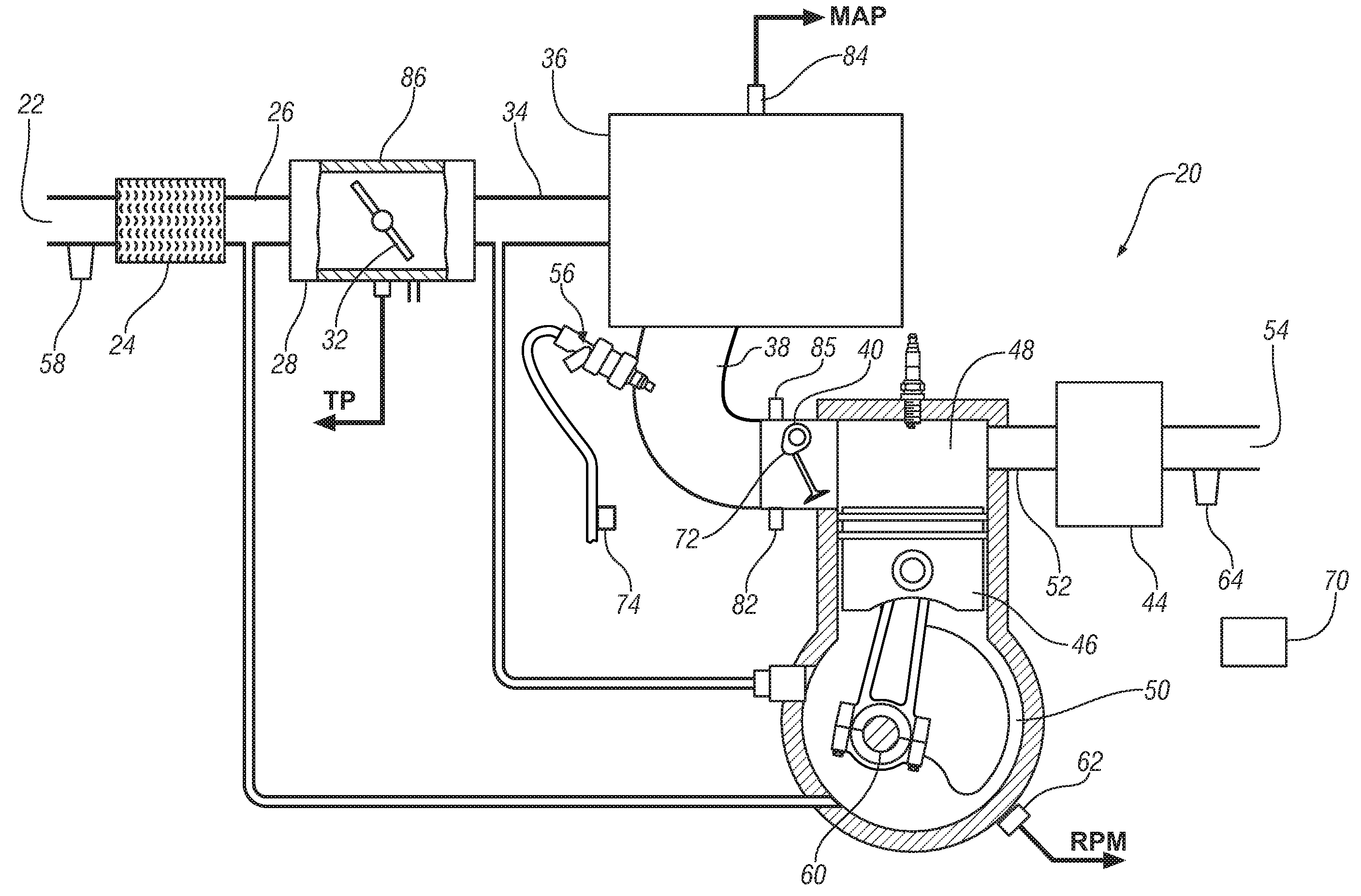
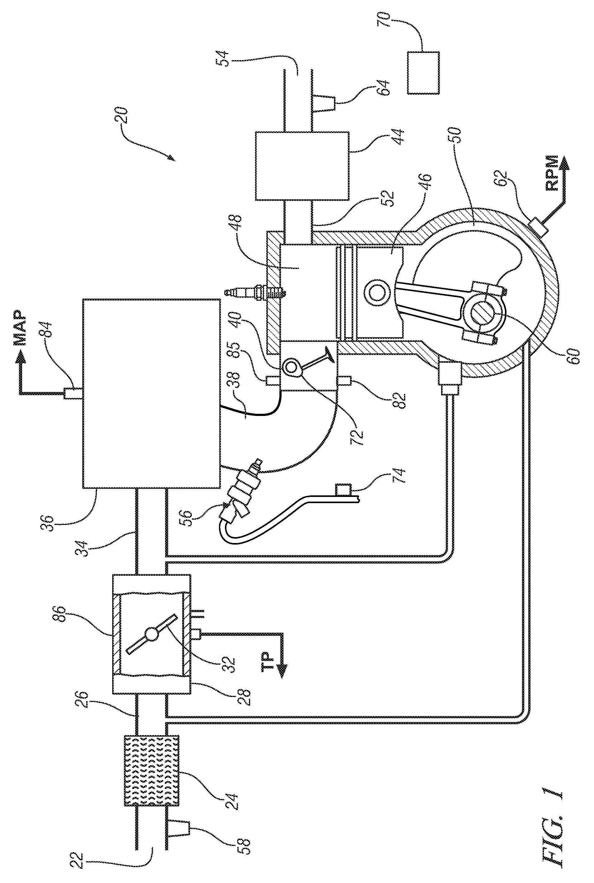
[0012]Turning now to FIG. 1, a schematic model of a spark ignited internal combustion engine system (System) 20 is illustrated. The System 20, in the most general sense, comprises all engine associated apparatus affecting or affected by gas mass flow and includes the operating environment or atmosphere from which and to which gas mass flows. The internal combustion engine includes a naturally aspirated or a boosted internal combustion engine. The atmosphere 66 is shown entering the system at the fresh air inlet 22.

[0013]The System includes a variety of pneumatic elements, each generally characterized by at least a pair of ports through which gas mass flows. For example, air induction including fresh air inlet 22, air cleaner 24, and intake duct 26 is a first general pneumatic element having ports generally corresponding to the air inlet 22 at one end and another port generally corresponding to the intake duct 26 at the other end. Another example of a pneumatic element is intake mani...


PUM


Abstract

A method of estimating an air charge in at least one combustion cylinder of an internal combustion engine includes calculating cylinder mass air flow based upon a modified volumetric efficiency parameter; and calculating the intake throttle mass air flow based upon a throttle air flow discharge parameter and a fuel enrichment factor. Three models including a mean-value cylinder flow model, a manifold dynamics model, and a throttle flow model are provided to estimate the air charge in the at least one combustion cylinder and to control delivery of fuel to the fuel delivery system.

Description

TECHNICAL FIELD[0001]The present invention is related to the field of engine controls for internal combustion engines and more particularly is directed toward estimation of throttle mass air flow as used in such controls.BACKGROUND OF THE INVENTION[0002]The basic objective for fuel metering in most gasoline engine applications is to track the amount of air in the cylinder with a predefined stoichiometric ratio. Therefore, precise air charge assessment is a critical precondition for any viable open loop fuel control policy in such engine applications. As the air charge cannot be measured directly its assessment, in one way or another, depends on sensing information involving a pressure sensor for the intake manifold, a mass air flow sensor upstream of the throttle plate, or both. The choice of a particular sensor configuration reflects a compromise between ultimate system cost and minimum performance requirements. Currently, high cost solutions involving both sensors are found in mar...

Claims


Application Information

Patent Timeline
Patent Type & Authority Applications(United States)
IPC IPC(8): F02D28/00G01M99/00
CPCF02D2200/0406F02D41/18
Inventor TURIN, RAYMOND CLAUDEZHANG, RONGCHANG, MAN-FENG
Owner GM GLOBAL TECH OPERATIONS LLC
Why Eureka
Try Eureka