Centrifugal separator for cleaning of gas

a centrifugal separator and gas cleaning technology, applied in centrifuges, separation processes, instruments, etc., can solve the problems of not having a reading device, unable to determine the rotary speed of the rotor, and having to include at least one reading device, so as to ensure the reliability of operation and the read number of revolutions, the effect of reliable and secure determination of the number of revolutions

Active Publication Date: 2009-01-29
ALFA LAVAL CORP AB
View PDF21 Cites 70 Cited by
  • Summary
  • Abstract
  • Description
  • Claims
  • Application Information

AI Technical Summary

Benefits of technology

[0006]The object of the invention is to provide a centrifugal separat...

Problems solved by technology

However, such a drive of the rotor gives no indication of the rotary speed of the rotor.
Such a rotary speed sensor has, however, the disadvantage that the reading device has to include at least some part projecting in thro...

Method used


Image

  • Centrifugal separator for cleaning of gas
  • Centrifugal separator for cleaning of gas

Examples


Embodiment Construction

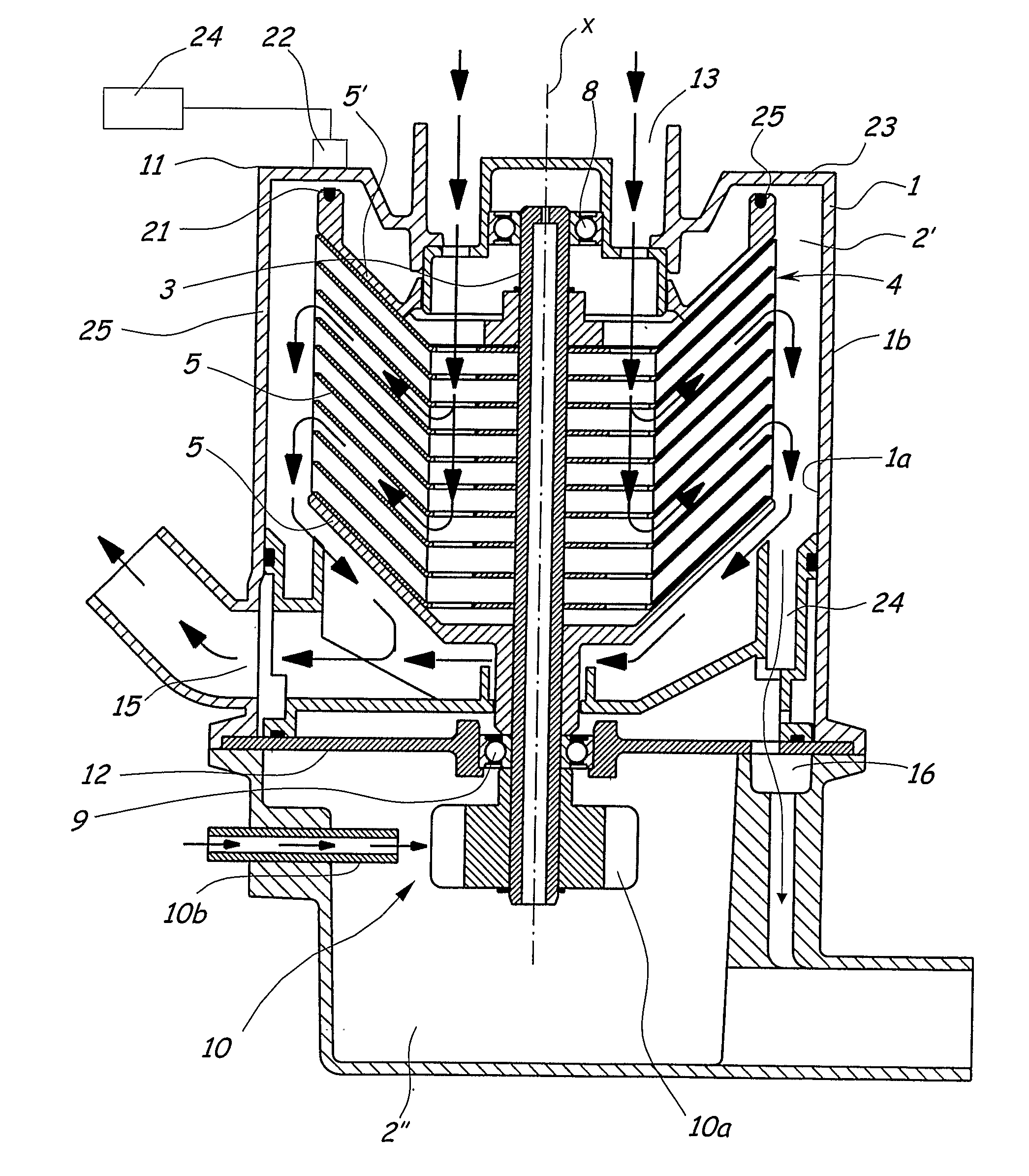
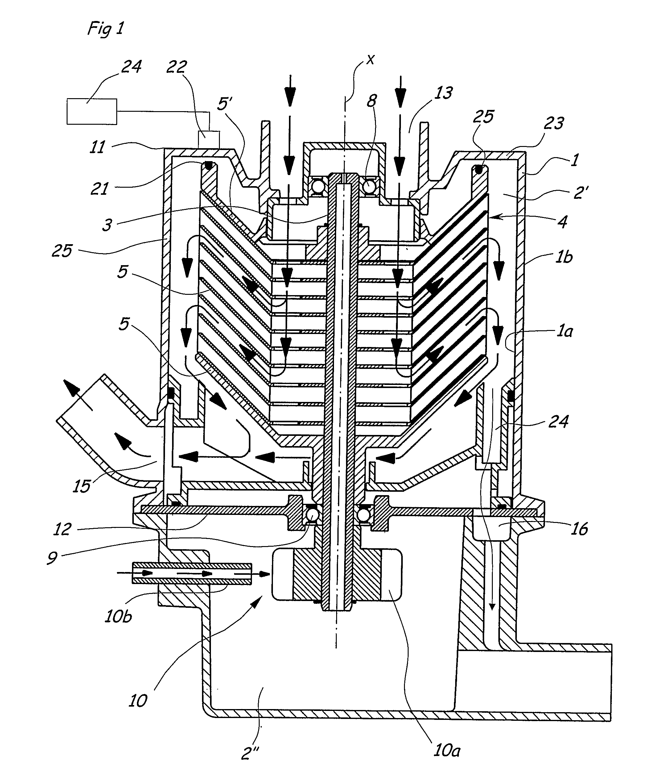
[0020]FIG. 1 discloses a centrifugal separator according to an embodiment of the invention. The centrifugal separator disclosed is intended for cleaning of gas and in particular crankcase gases from internal combustion engines. The combustion engines may be such for driving of motor vehicles or stationary combustion engines, for instance for generating electric energy. The centrifugal separator is also applicable to cleaning of other gases, such as air in and around machine tools in the engineering industry. The application areas mentioned comprise cleaning of gases containing contaminants, in particular liquid contaminants in the form of oil mist or oil droplets. The centrifugal separator according to the present invention is especially suitable for separation of such oil from the air or the gas.

[0021]The centrifugal separator disclosed comprises a stationary casing 1, which defines an inner space 2′. The stationary casing 1 has an inner wall surface 1a, which faces the inner space...


PUM

PropertyMeasurementUnit
Weightaaaaaaaaaa
Magnetic fieldaaaaaaaaaa
Speedaaaaaaaaaa

Abstract

The invention refers to a centrifugal separator comprising a stationary casing defining an inner space, a spindle and a rotating member, which is attached to the spindle and arranged to rotate around an axis of rotation with a rotary speed. The rotating member comprises a number of separating discs which are provided in the inner space. A drive member drives the spindle and the rotating member with said rotary speed. A sensor device senses the rotation of the rotating member in relation to the casing. The sensor device comprises at least one transmitter element which is provided in the inner space on the rotating member and a receiver element which is provided at the casing and arranged to sense the transmitter element. The receiver element is provided on the casing outside the inner space.

Description

FIELD OF THE INVENTION[0001]The present invention refers to a centrifugal separator comprising a stationary casing defining an inner space, a spindle, a rotating member, which is attached to the spindle and arranged to rotate around an axis of rotation with a rotary speed, wherein the rotating member comprises a number of separating discs which are provided in the inner space, a drive member for driving the spindle and the rotating member with said rotary speed, a sensor device for sensing the rotation of the rotating member in relation to the casing, wherein the sensor device comprises at least one transmitter element, which is provided in the inner space on the rotating member, and a receiver element, which is provided at the casing and arranged to sense the transmitter element.BACKGROUND OF THE INVENTION[0002]This invention refers in particular to a centrifugal separator intended for cleaning of crankcase gases from a combustion engine, especially for the driving of vehicles. Suc...

Claims


Application Information

Patent Timeline
IPC IPC(8): B01D19/00B04B15/00
CPCB01D45/14B04B5/005B04B5/12B04B7/06Y10S55/19B04B2005/125F01M2013/0422G01P3/487B04B13/00B04B1/08B04B13/003
Inventor HALLGREN, INGVARELIASSON, THOMASLARSSON, LEIF
Owner ALFA LAVAL CORP AB
Why Eureka
Try Eureka