Eureka AIR delivers breakthrough ideas for toughest innovation challenges, trusted by R&D personnel around the world.

Generating signal bearing art using stipple, voronoi and delaunay methods and reading same

Active Publication Date: 2019-12-12
DIGIMARC CORP
View PDF0 Cites 18 Cited by
  • Summary
  • Abstract
  • Description
  • Claims
  • Application Information

AI Technical Summary

Benefits of technology

The patent text discusses the challenges of using conventional barcodes in package and label designs, such as taking up valuable space and causing potential confusion and complexity in image processing. It introduces the concept of digital watermarks as a solution that can be embedded within other images on the object to improve automatic data capture and optical code insertion methods that improve visual quality and robustness. The technical effects of the patent include reducing the visual impact of codes, improving reliability and visibility of code elements, and facilitating reliable data capture from arbitrary and partial views of the object.

Problems solved by technology

This growing use of barcodes poses a number of challenges for package and label designs.
Second, it creates a potential for confusion and complexity in image processing for image-based scanners, which are rapidly replacing laser scanners.
Third, to reduce the visual impact of these codes, they are often reduced in size and confined to difficult to find locations on the objects.
This makes them less reliable, and harder for users and machine vision equipment to locate and read reliably.
Digital watermarks may be hidden within other images on the object, and thus not occupy valuable, dedicated space.
One challenge is the formation of minimally invasive optical codes for host image areas lacking image content that can mask the optical code or even act as a carrier of it.
However, there are often limits to color selection and resolution that preclude these options.
Many objects are printed or marked with technology that does not allow for color selection, and that does not reliably mark dots below a minimum dot size.
Other examples include commercial printing of small packages that use techniques like dry offset or flexographic printing, which are incapable of rendering with high quality and consistency at high resolution and small dot sizes.
Moreover, there are often restrictions based on design and cost constraints of using additional inks.
Finally, even if rendering equipment can leverage higher resolution and smaller dot marking, and various color inks, the image capture infrastructure or mode of image capture may be incapable of capturing higher resolution or color information.
Another persistent challenge is the need to reliably read data from increasingly smaller spatial areas.
The demand for increasing data capacity is fundamentally at odds with reliable recovery of that data from a limited area.

Method used


Image

  • Generating signal bearing art using stipple, voronoi and delaunay methods and reading same
  • Generating signal bearing art using stipple, voronoi and delaunay methods and reading same
  • Generating signal bearing art using stipple, voronoi and delaunay methods and reading same

Examples


Embodiment Construction

[0066]This specification details embodiments of the technology with reference to flow diagrams and narrative descriptions. The diagrams and descriptions are implemented with processing modules that are most commonly realized by software instructions for configuring programmable hardware devices. In some embodiments, such software instructions are converted to firmware for integration into printers and scanners, or converted into digital logic circuitry.

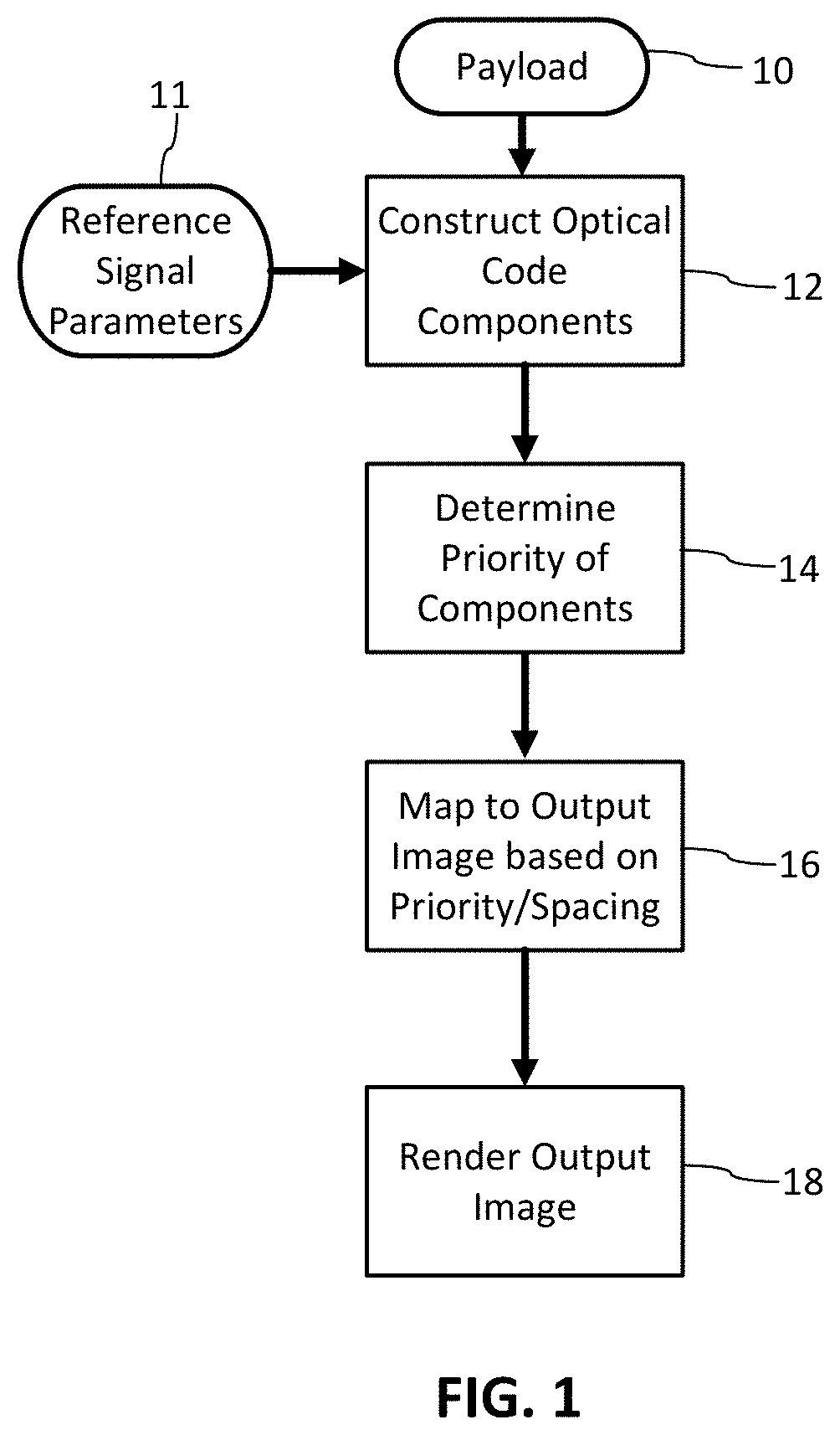
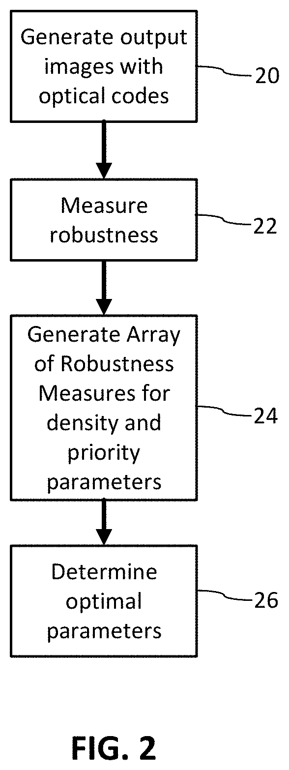
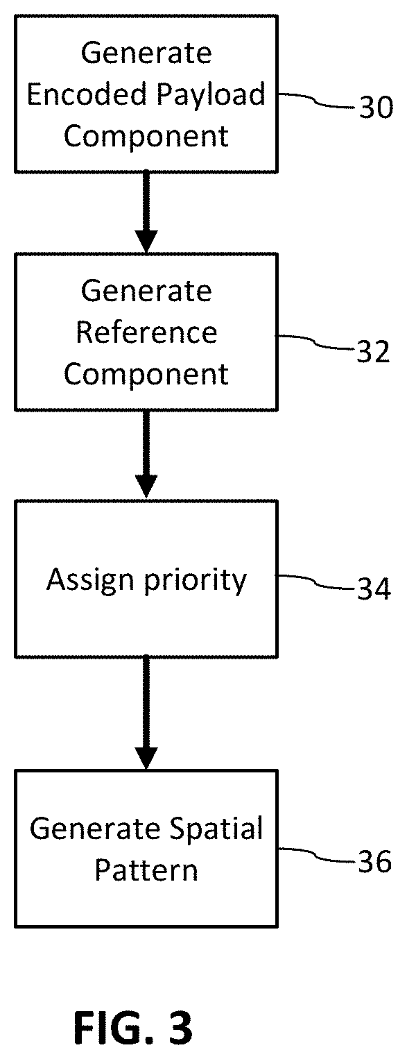
[0067]FIG. 1 is a diagram of a method of generating an optical code with variable spatial density to adapt the code for visual quality and reliability constraints. An objective is to generate an optical code for insertion into an image or other carrier such that the parameters of the optical code are optimized. These parameters include robustness and visual quality. The method achieves improved robustness by determining a priority of optical message components that attains or surpasses robustness metrics while also providing desired s...


PUM


Abstract

Optical code signal components are generated and then transformed into signal bearing art that conveys machine readable data. The components of an optical code are optimized to achieve improved signal robustness, reliability, capacity and / or visual quality. An optimization program can determine spatial density, dot distance, dot size and signal component priority to optimize robustness. An optical code generator transforms tiles of an optical code or image embedded with the optical code into signal-bearing art using stipple, Voronoi, Delaunay or other graphic drawing methods so as to retain prioritized components of the optical code. The optical code is merged into a host image, such as imagery, text and graphics of a package or label, or it may be printed by itself, e.g., on an otherwise blank label or carton. A great number of other features and arrangements are also detailed.

Description

RELATED APPLICATION DATA[0001]This application claims priority to provisional application 62 / 682,731, filed Jun. 8, 2018, which is incorporated by reference.[0002]This application is related to U.S. application Ser. No. 16 / 405,621, filed May 7, 2019, and International Applications PCT / US18 / 64516, filed Dec. 7, 2018, and PCT / US19 / 19410, filed Feb. 25, 2019, which are hereby incorporated by reference.TECHNICAL FIELD[0003]The present technology relates, generally, to image processing to generate machine-readable optical codes for printing (optionally after merging with host image content), complementary robustness measurements for optimizing the optical codes, and optical code readers for reliably and efficiently reading such codes from objects.[0004]In part, this application concerns enhancements and improvements to the sparse signaling technologies detailed in applicant's U.S. Pat. No. 9,635,378 and publication 20170024840, which are incorporated herein by reference.BACKGROUND AND SU...

Claims


Application Information

Patent Timeline
IPC IPC(8): G06T1/00H04N1/32
CPCG06T1/0028G06T1/005H04N1/32309G06T2201/0062H04N1/3232G06T2201/0202G06T1/0064G06T2201/0601G06T2201/0061
Inventor KAMATH, AJITH M.
Owner DIGIMARC CORP
Why Eureka
Eureka Blog
Learn More