Image reading device

Active Publication Date: 2007-01-04
BROTHER KOGYO KK
View PDF5 Cites 25 Cited by
  • Summary
  • Abstract
  • Description
  • Claims
  • Application Information

AI Technical Summary

Problems solved by technology

Since such a dedicated code reading device is designed only for obtaining codes, it is not cost-effective to introduce a dedicated code reading device to an office particularly in the case where frequency of usage of the dedicated reading device is low.
However, such a try will not achieve success because light from a light source of the scanner reflects from a protective layer or a reflective layer, which forms a LCD screen unit of a mobile phone, and such reflection makes it difficult to appropriately read an image displayed on the LCD screen of the mobile phone.
Use of a general-purpose

Method used


Image

  • Image reading device
  • Image reading device
  • Image reading device

Examples


Embodiment Construction

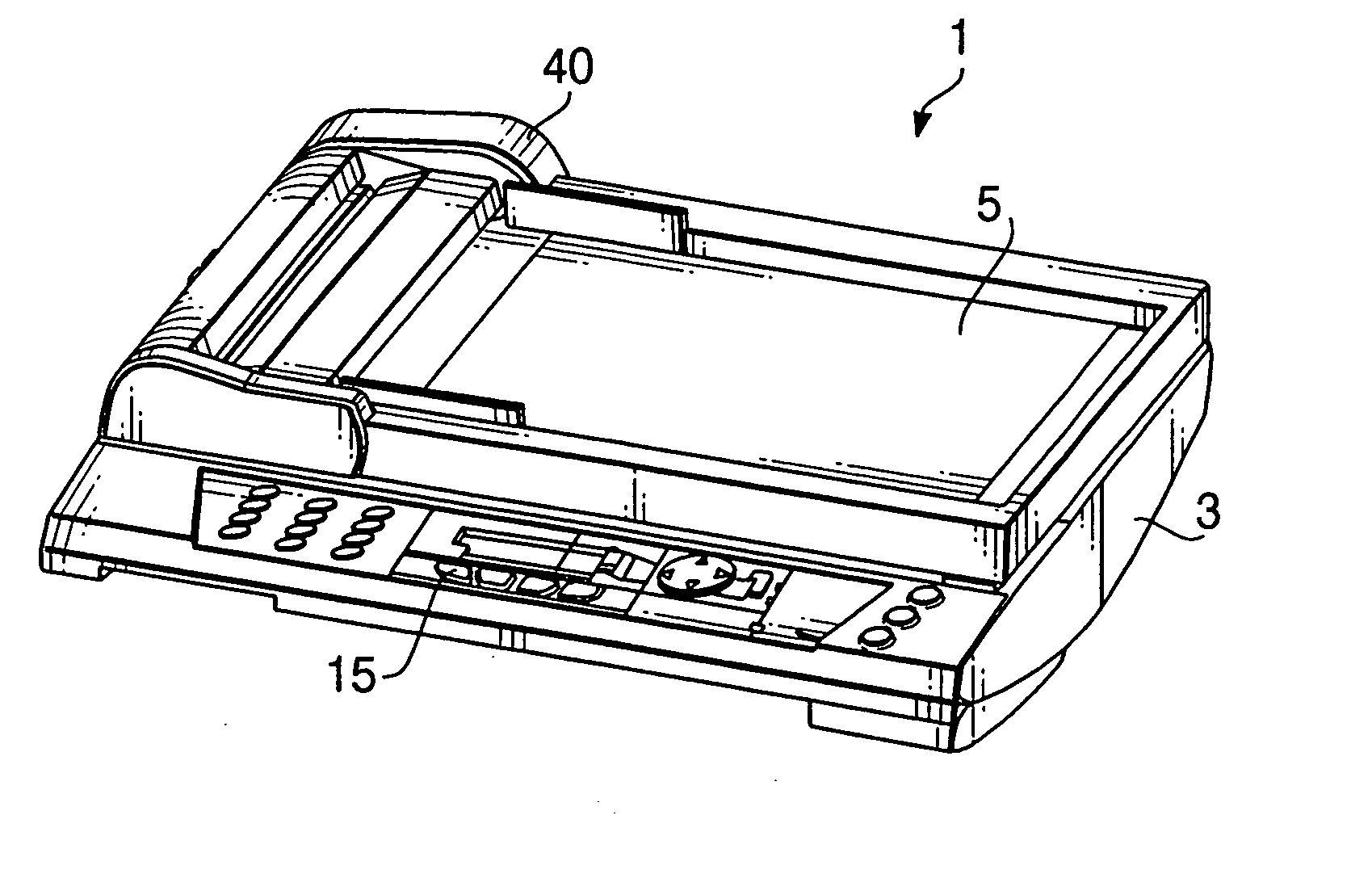
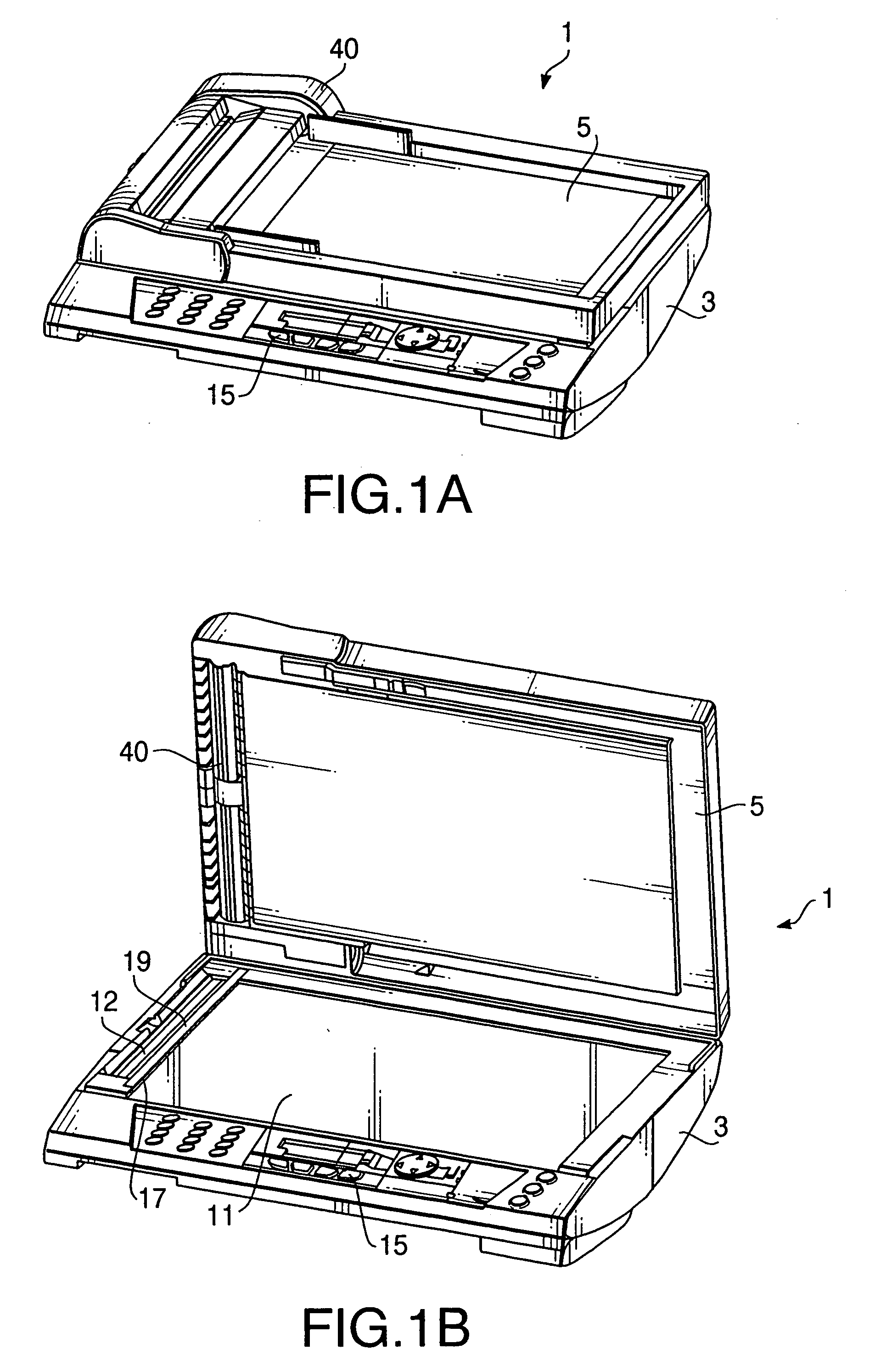
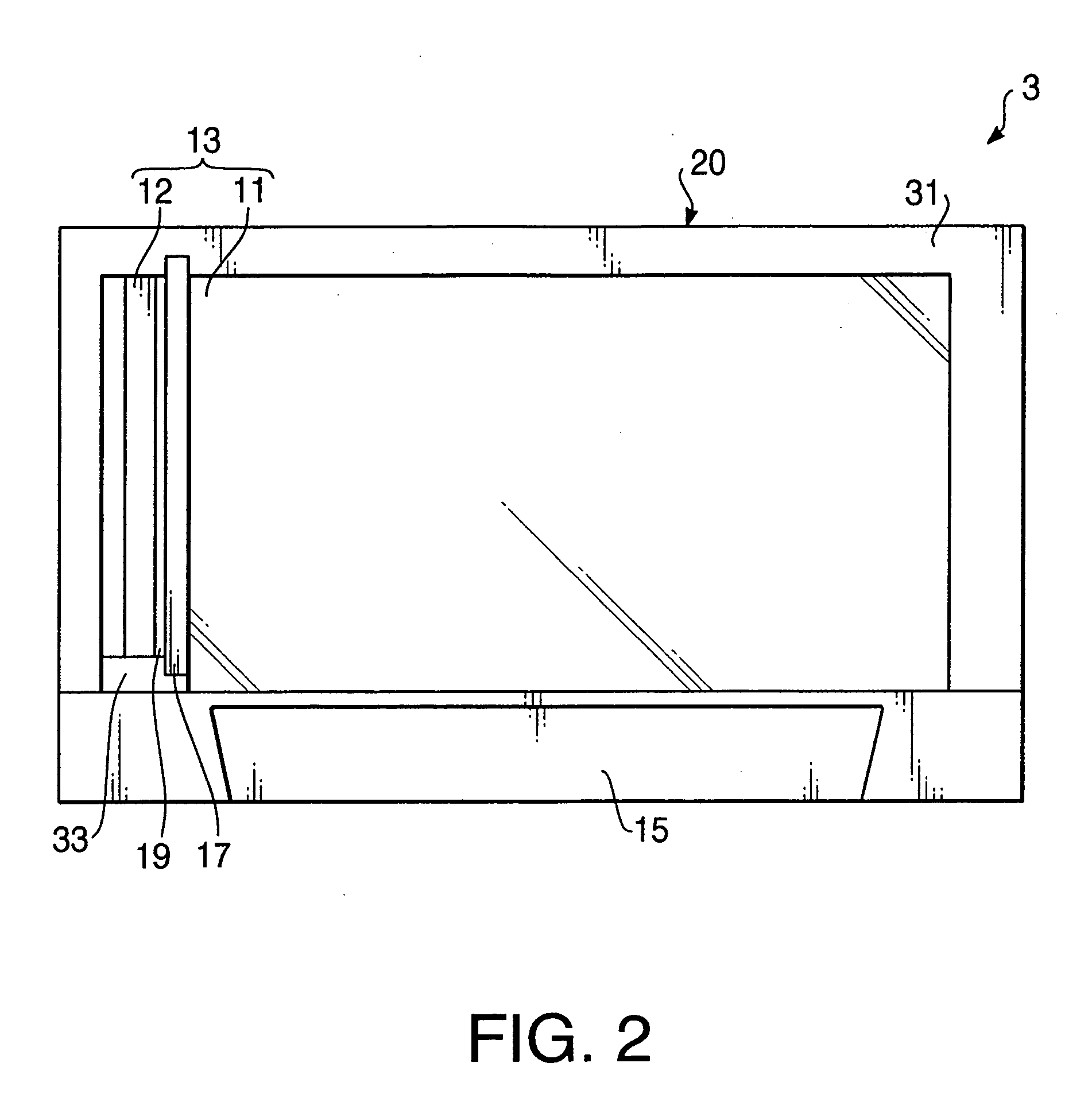
[0019] General Overview

[0020] According to an aspect of the invention, there is provided an image reading device, which is provided with an illuminating unit that illuminates an object, a reading unit that forms an image of the object based on light from the object, and an illumination prohibition unit that prohibits the illumination unit from illuminating the object if the illumination prohibition unit receives a command for changing to a code reading mode in which a code formed by a pictorial pattern displayed on a screen of a device is read as the object.

[0021] Since the illumination of the illuminating unit is prohibited if the command for changing to the code reading mode is received, the screen is prevented from reflecting light and it is possible to reliably read the code displayed on the screen. Such an advantage is enhanced if the screen of the device is configured to display an image by lighting the screen without utilizing reflections of outside light.

[0022] According ...


PUM


Abstract

There is provided an image reading device, which is provided with an illuminating unit that illuminates an object, a reading unit that forms an image of the object based on light from the object, and an illumination prohibition unit that prohibits the illumination unit from illuminating the object if the illumination prohibition unit receives a command for changing to a code reading mode in which a code formed by a pictorial pattern displayed on a screen of a device is read as the object.

Description

CROSS-REFERENCE TO RELATED APPLICATION [0001] This application claims priority under 35 U.S.C. §119 from Japanese Patent Application No. 2005-130291, filed on Apr. 27, 2005. The entire subject matter of the application is incorporated herein by reference.BACKGROUND [0002] 1. Technical Field [0003] Aspects of the present invention relate to an image reading device capable of receiving light reflected from an object and forming an image of the object in accordance with the received light. [0004] 2. Description of Related Art [0005] Image reading devices, such as a scanner, capable of reading an image formed on a print medium are widely used. In general, the scanner is provided with a light source, a glass plate on which a print medium is placed, and an image sensor. In order to obtain an image formed on the print medium, the light source illuminates the print medium from the lower side of the glass plate, and the image sensor (e.g. a line sensor) is moved from one edge of the glass pl...

Claims


Application Information

Patent Timeline
IPC IPC(8): G06K7/10
CPCH04N1/00795H04N1/00806H04N1/00811H04N1/40056H04N1/00827H04N1/00997H04N1/00822
Inventor SUZUKI, MASAHIOHARA, KIYOTAKA
Owner BROTHER KOGYO KK
Why Eureka
Try Eureka