Point-of-transaction, dual window workstation for imaging indicia with a single imager and a stationary optical system

a workstation and imaging indicia technology, applied in the field of point-of-transaction, dual-window workstations for imaging indicia, can solve the problems of insufficient scan zone coverage, variable symbol location and difficult to predict in advance, and achieve the effect of significant reducing workstation costs and enhancing imaging responsiveness

Inactive Publication Date: 2012-05-17
SYMBOL TECH INC
View PDF0 Cites 24 Cited by
  • Summary
  • Abstract
  • Description
  • Claims
  • Application Information

AI Technical Summary

Benefits of technology

[0011]Thus, the first optical subsystem twice splits the field of view of the single imager as a result of said first and second splits into two light collection regions of substantially equal smaller spatial volume and two more light collection regions of substantially equal larger spatial volume. All four of the light collection regions pass through the horizontal window along different intersecting directions to cover four sides of the product. Thus, one larger light collection region is customized to read the left side and the bottom of the product; another larger light collection region is customized to read the right side and the bottom of the product; and each smaller light collection region is customized to read the front of the product. The smaller and the larger light collection regions are appropriately sized to perform their different tasks. All four of the light collection regions are derived from just the one single imager, thereby significantly reducing workstation costs. All four of these light collection regions, together with the additional light collection region or regions described below that pass through the upright window, substantially fully occupy the scan zone. As a result, any dead areas in the scan zone in which indicia cannot be read are significantly minimized.
[0012]The second optical subsystem, in one embodiment, includes a third stationary reflecting surface on the aforementioned optical splitter and located above still another portion of the sensor array for splitting the field of view of the single imager into a third subfield of view, and one or more fold mirrors positioned relative to the third reflecting surface for reflecting the third subfield of view as an additional light collection region through the other window, e.g., the upright window. The entire third subfield of view may be reflected through the upright window, or the third subfield of view may be split again into a plurality of additional light collection regions, in which the back and top of the product are covered. Thus, indicia on the fifth and the sixth side of the product are read. In this embodiment, the light collection regions derived from the field of view of the single imager simultaneous image the indicia through both windows, thereby enhancing imaging responsiveness.

Problems solved by technology

All these factors make the symbol location variable and difficult to predict in advance.
However, such light collection regions produced by splitting the field of view in the known imager-based workstation do not fully occupy the scan zone.
As a result, the scan zone does not have full coverage and has dead areas in which indicia cannot be read.
Also, moving the entire field of view of an imager to successively face each window of the workstation takes time and requires synchronization at least between the moving component and the imager.
In some applications, it might be desirable for increased imaging responsiveness to image the indicia simultaneously through both windows and, therefore, moving the entire field of view with its inherent timing delay is disadvantageous.
In addition, the moving component, as compared to a stationary component, has a shorter working lifetime, is more prone to failure, and often generates dust that can deposit and build up on optical surfaces, thereby degrading overall imaging performance and efficiency.

Method used


Image

  • Point-of-transaction, dual window workstation for imaging indicia with a single imager and a stationary optical system
  • Point-of-transaction, dual window workstation for imaging indicia with a single imager and a stationary optical system
  • Point-of-transaction, dual window workstation for imaging indicia with a single imager and a stationary optical system

Examples


Embodiment Construction

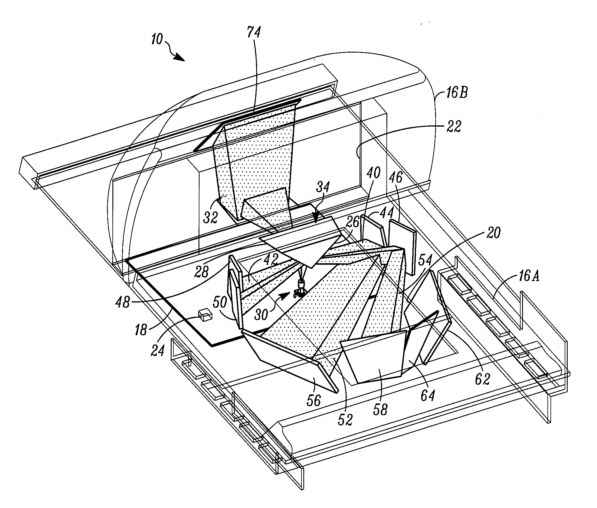
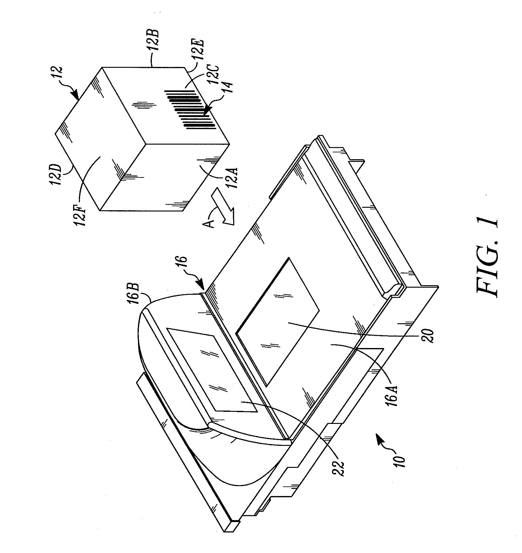
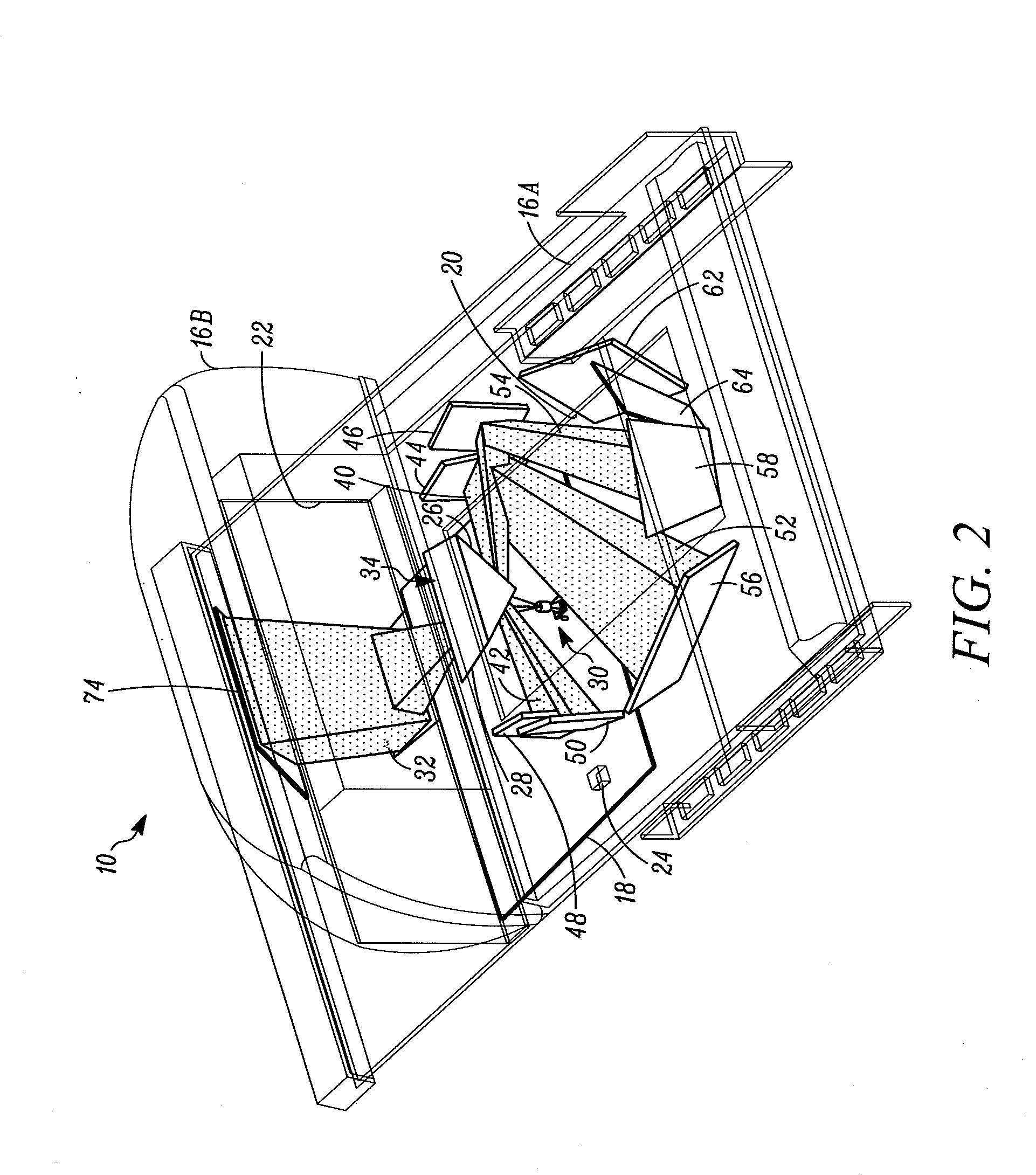
[0028]FIG. 1 depicts a dual window, bi-optical, point-of-transaction workstation 10 for electro-optically imaging indicia 14 or targets, such as the illustrated UPC symbol described above, associated with multi-sided, three-dimensional products 12, and is typically used by retailers to process transactions involving the purchase of the products 12 bearing, or printed with, the identifying indicia 14. The workstation 10 includes a housing 16 having a generally horizontal window 20 located in a generally horizontal plane and supported by a horizontal housing portion 16A, and an upright window 22 located in a generally upright plane that intersects the generally horizontal plane and supported by a raised housing portion 16B. The upright plane may lie in a vertical plane, or be slightly rearwardly or forwardly inclined relative to the vertical plane. The upright window 22 is preferably recessed within the housing portion 16B to resist scratching. The products are passed by an operator o...


PUM


Abstract

A bi-optical, dual window, point-of-transaction workstation images indicia associated with products with a single, solid-state imager that captures return light from the indicia over a field of view. A first optical subsystem is stationarily supported by the workstation and directs at least a part of the field of view of the imager as a first light collection region or regions passing through one of the windows. A second optical subsystem is also stationarily supported by the workstation and directs at least a part of the field of view of the imager as a second light collection region or regions passing through the other of the windows. A controller controls the imager and processes the captured return light in at least one of the light collection regions.

Description

BACKGROUND OF THE INVENTION[0001]It is known to use laser-based and / or imager-based readers in a dual window or bi-optical workstation to electro-optically read indicia, such as bar code symbols, associated with three-dimensional products to be identified and processed, e.g., purchased, at a point-of-transaction workstation provided at a countertop of a checkout stand in supermarkets, warehouse clubs, department stores, and other kinds of retailers. The products are typically slid or moved across, or presented to a central region of, a generally horizontal window that faces upwardly above the countertop and / or a generally vertical or upright window that vertically faces a user at the workstation. When at least one laser scan line generated by a laser-based reader sweeps over a symbol and / or when return light from the symbol is captured over a field of view by a solid-state imager of an imager-based reader, the symbol is then processed, decoded and read, thereby identifying the produ...

Claims


Application Information

Patent Timeline
Patent Type & Authority Applications(United States)
IPC IPC(8): G06K7/10
CPCG06K7/10722
Inventor DRZYMALA, MARKBARKAN, EDWARD
Owner SYMBOL TECH INC
Why Eureka
Try Eureka