Variable Optical Attenuator

a variable optical and attenuator technology, applied in the field of attenuating optical devices, can solve the problems of voa measurement error, device not very compact, and possibility of backreflection into fibers,

Inactive Publication Date: 2009-04-23
JDS UNIPHASE CORP
View PDF11 Cites 11 Cited by
  • Summary
  • Abstract
  • Description
  • Claims
  • Application Information

AI Technical Summary

Benefits of technology

[0013]The disadvantages of the approach illustrated in FIGS. 1A, 1B, and FIG. 2 are overcome by the present invention. The goal of the present invention is to provide a VOA-tap hybrid device having high fidelity of optical power measurement, high reliability, low backreflection, and compact size. Preferably, the size of the device has to be compact enough so that a standard small form pluggable (SFP) package can be used as a housing of the device.

Problems solved by technology

This is not an easy requirement because optical taps usually use a small fraction of the total power, for example 5%, to make a measurement representative of total optical power.
The disadvantage of the approach based on splicing a VOA and an optical tap is that the resulting device is not very compact.
Specifically, one drawback is that placing an object near a fiber tip creates a possibility of backreflection into that fiber.
Since the fraction of the optical power of light at a photodetector is small, for example it can be 1%-5% of the optical power of incoming light, even a minute amount of scattered light reaching the photodetector, for example 0.5% of the optical power of incoming light, would result in an error in measurement of the optical power of light passing through the VOA 420.
Further, disadvantageously, when the shutter 423 is used to attenuate both free-space propagating beams associated with the fibers 101 and 102, another potential source of error in the measurement of optical power exists due to the following.

Method used


Image

  • Variable Optical Attenuator
  • Variable Optical Attenuator
  • Variable Optical Attenuator

Examples


Embodiment Construction

[0041]While the present teachings are described in conjunction with various embodiments and examples, it is not intended that the present teachings be limited to such embodiments. On the contrary, the present teachings encompass various alternatives, modifications and equivalents, as will be appreciated by those of skill in the art. Like numbers refer to like elements throughout.

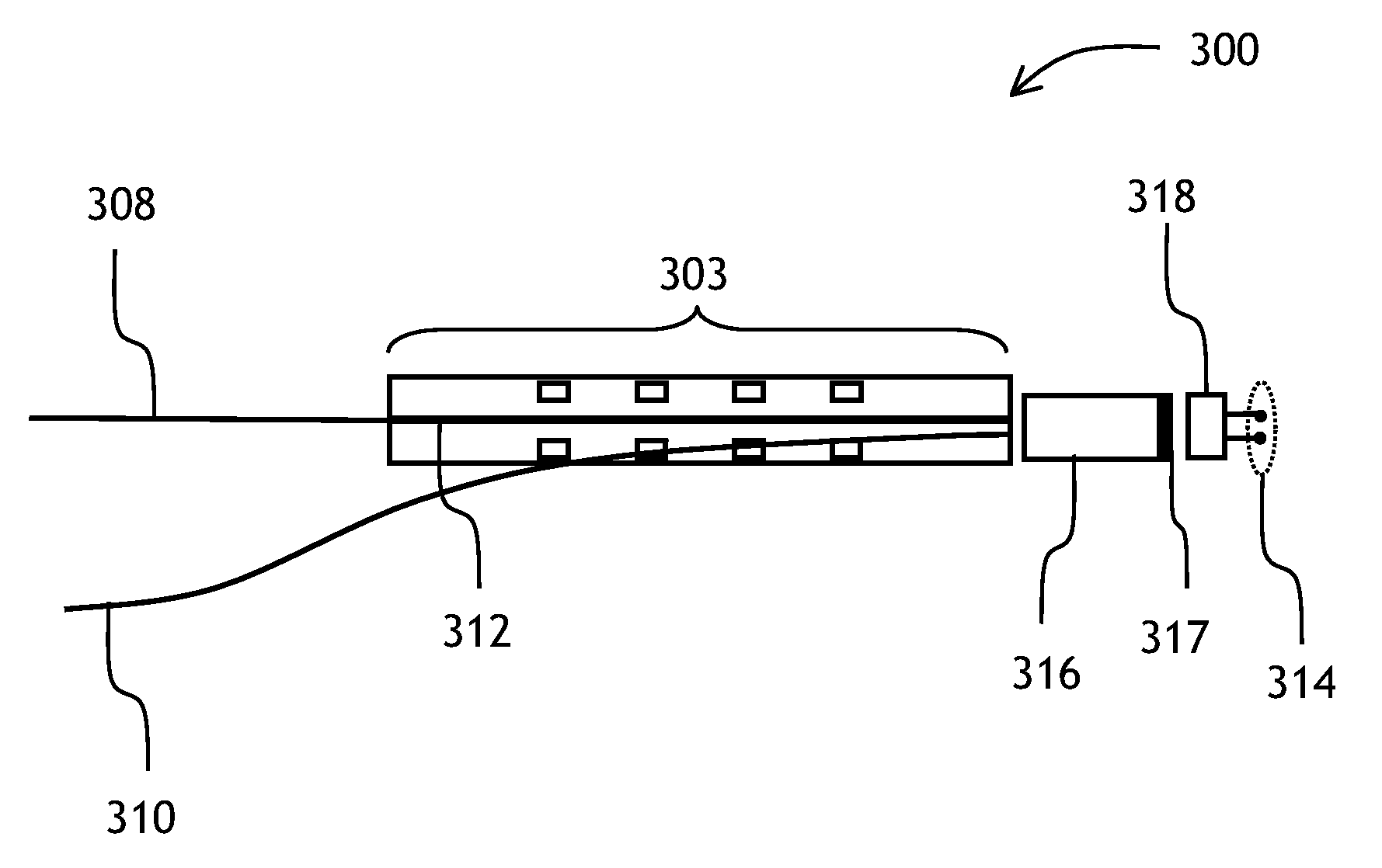
[0042]Referring now to FIG. 3A, a plan view of one preferred embodiment of the VOA—optical tap device 300 of the instant invention is shown comprising a waveguide optical attenuator 303 having a planar waveguide 312, a GRIN lens 316 having a beamsplitter coating 317, and a photodetector 318 having electrical contacts 314. The waveguide optical attenuator 303 attenuates light by a mechanism of free carrier absorption, wherein the free carriers are injected into a region of the waveguide 312 by supplying an electrical current to the waveguide 303. An input optical fiber 308 is butt-coupled to the planar wavegu...


PUM


Abstract

A compact variable optical attenuator having optical-tap functionality is described comprising a planar waveguide attenuator, a lens, and a photodetector. Input and output waveguides are located close to the optical axis of the lens, which reduces optical aberrations and insertion loss. The waveguide attenuator works by light absorption with virtually no scattered light present, which improves fidelity of measurements of the tapped optical power by the photodetector. The entire tap-attenuator assembly is packaged into a small form pluggable (SFP) package having two optical connectors.

Description

CROSS-REFERENCE TO RELATED APPLICATIONS[0001]The present invention claims priority from 60 / 981,647, filed Oct. 22, 2007, which is incorporated herein by reference.TECHNICAL FIELD[0002]The present invention is related to optical devices for attenuating light and, in particular, to compact variable optical attenuators having an additional function of measuring optical power of light.BACKGROUND OF THE INVENTION[0003]In optical communication networks, light signals are modulated with a binary stream of data and transmitted through optical fibers spanning from one location to another. On their way from a source to a destination, the light signals can be amplified, multiplexed, routed, and passed between various fiber spans. All these operations reduce optical power of the signals, with the exception of amplification, which boosts the power back to an acceptable level. Overall, the optical power of the signals is maintained within a certain range, in order for a signal to be properly ampl...

Claims


Application Information

Patent Timeline
Patent Type & Authority Applications(United States)
IPC IPC(8): G02B6/26
CPCG02B6/4201G02B6/26G02B6/4287G02B6/426G02B6/424
Inventor HUANG, QINGXIAO, CHANGCHEN, XIAOLINYANG, YATAO
Owner JDS UNIPHASE CORP
Why Eureka
Try Eureka