Driving Circuit Board Assembly for Motor

Active Publication Date: 2009-06-18
SUNONWEALTH ELECTRIC MACHINE IND
View PDF9 Cites 10 Cited by
  • Summary
  • Abstract
  • Description
  • Claims
  • Application Information

AI Technical Summary

Benefits of technology

[0006]An objective of the present invention is to provide a driving circuit board assembly for a motor that

Problems solved by technology

However, when the motor 9 has a high output power rated, with the electronic elements 8 densely arranged on one side of the driving circuit board 91 and the other side of the driving circuit board 91 being close to the stator 92, the increase of the driving current of the driving circuit board 91 causes a lot of heat, which is generated b

Method used


Image

  • Driving Circuit Board Assembly for Motor
  • Driving Circuit Board Assembly for Motor
  • Driving Circuit Board Assembly for Motor

Examples


first embodiment

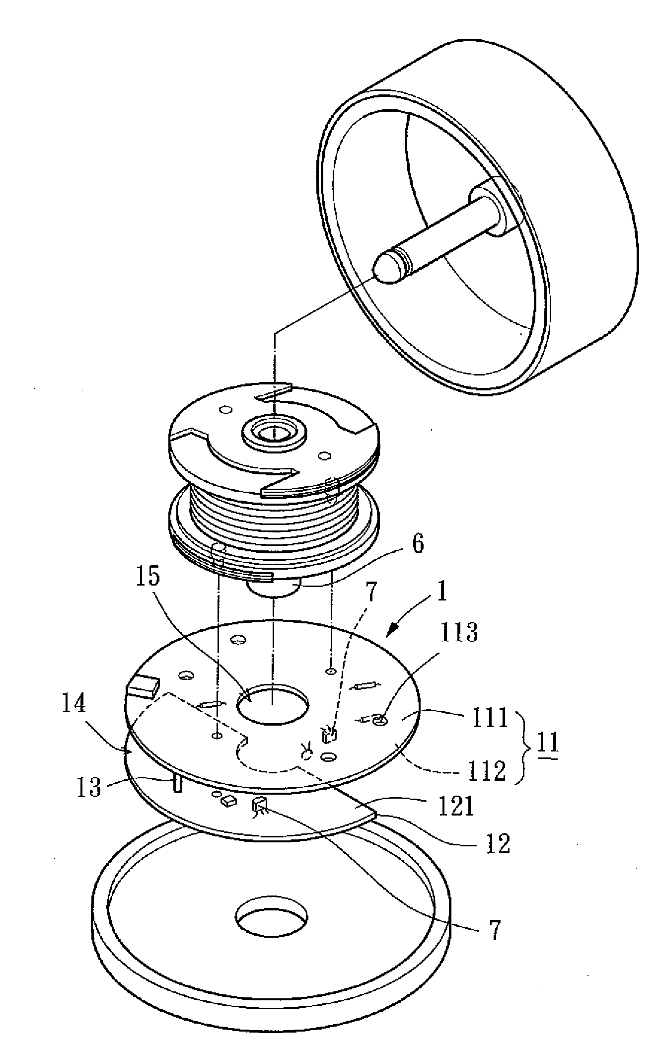
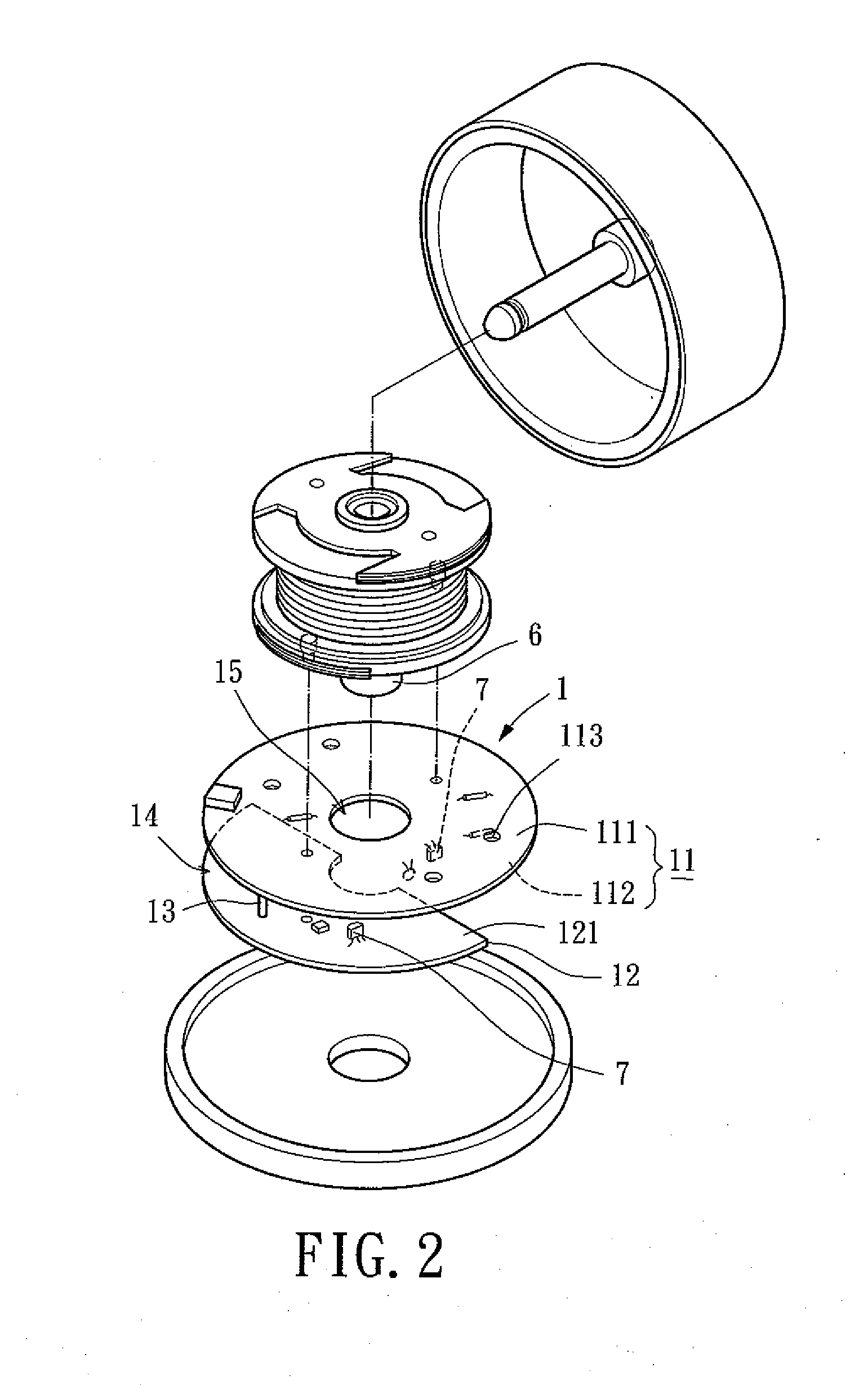
[0019]Referring to FIGS. 2 and 3, a driving circuit board assembly 1 for a motor of a first embodiment according to the preferred teachings of the present invention includes first and second driving circuit boards 11 and 12 stacked and spaced in an axial direction of a motor. According to the preferred form shown, a conductive connecting member 13, for example in the form of a conductive rod, is mounted between the first and second driving circuit boards 11 and 12 to provide a spacing 14 between the first and second driving circuit boards 11 and 12. The first driving circuit 11 includes opposite first and second faces 111 and 112 on which a plurality of electronic elements 7 are mounted. The first driving circuit board 11 further includes a mounting hole 15 extending from the first face 111 through the second face 112. The mounting hole 15 is preferably in a center of the first driving circuit board 11 and allows the first driving circuit board 11 to be mounted around an axle tube 6...

second embodiment

[0021]FIGS. 4 and 5 show a driving circuit board assembly 2 for a motor of a second embodiment according to the preferred teachings of the present invention. According to the preferred form shown, the driving circuit board assembly 2 includes first and second driving circuit boards 21 and 22 and a conductive connecting member 23 interconnected between the first and second driving circuit boards 21 and 22. According to the most preferred form shown, the first and second driving circuit boards 21 and 22 and the conductive connecting member 23 are integral with each other as a single continuous monolithic piece and made of a flexible material such as fiberglass. The conductive connecting member 23 extends from an outer periphery of the first driving circuit board 21 to an outer periphery of the second driving circuit board 22. The first driving circuit board 21 includes opposite first and second faces 211 and 212 on which a plurality of electronic elements 7 are mounted. The first driv...

third embodiment

[0023]FIGS. 7 and 8 show a driving circuit board assembly 3 for a motor of a third embodiment according to the preferred teachings of the present invention. According to the preferred form shown, the driving circuit board assembly 3 includes first, second, and third driving circuit boards 31, 32, and 33, a first conductive connecting member 34 interconnected between the first and second driving circuit boards 31 and 32, and a second conductive connecting member 34, interconnected between the second and third driving circuit boards 32 and 33. According to the most preferred form shown, the first, second, and third driving circuit boards 31, 32, 33 and the first and second conductive connecting member 34, 34′ are integral with each other as a single continuous monolithic piece and made of a flexible material such as fiberglass. The first conductive connecting member 34 extends from an outer periphery of the first driving circuit board 31 to an outer periphery of the second driving cir...


PUM


Abstract

A driving circuit board assembly for a motor includes a plurality of driving circuit boards having a plurality of faces for mounting a plurality of electronic elements thereon. The driving circuit boards are stacked in an axial direction of a motor. Two of the driving circuit boards adjacent to each other are spaced by a conductive connecting member that is in electrical connection with the two driving circuits.

Description

BACKGROUND OF THE INVENTION[0001]1. Field of the Invention[0002]The present invention relates to a driving circuit board assembly for a motor and, more particularly, to a driving circuit board assembly including a plurality of axially spaced driving circuit boards.[0003]2. Description of Related Art[0004]FIG. 1 of the drawings illustrates a conventional motor 9 including a driving circuit board 91, a stator 92, and a rotor 93. The driving circuit board 91 includes a plurality of electronic elements 8 such as power electronics switches, resistors, capacitors, Hall ICs, pulse-width-modulation ICs, etc. The driving circuit board 91 is electrically connected to the stator 92 to feed the stator 92 with a driving current for creating a magnetic field to drive the rotor 93.[0005]However, when the motor 9 has a high output power rated, with the electronic elements 8 densely arranged on one side of the driving circuit board 91 and the other side of the driving circuit board 91 being close to...

Claims


Application Information

Patent Timeline
IPC IPC(8): H05K1/14H05K7/20H02K11/00
CPCH02K5/1675H02K11/0073H02K2211/03H05K2201/09063H05K1/189H05K2201/042H05K1/144H02K11/33
Inventor HORNG, ALEXHONG, CHING-SHEN
Owner SUNONWEALTH ELECTRIC MACHINE IND
Why Eureka
Try Eureka