Peak detector using charge pump and burst-mode transimpedance amplifier

Active Publication Date: 2016-04-28
ELECTRONICS & TELECOMM RES INST
View PDF8 Cites 10 Cited by
  • Summary
  • Abstract
  • Description
  • Claims
  • Application Information

AI Technical Summary

Benefits of technology

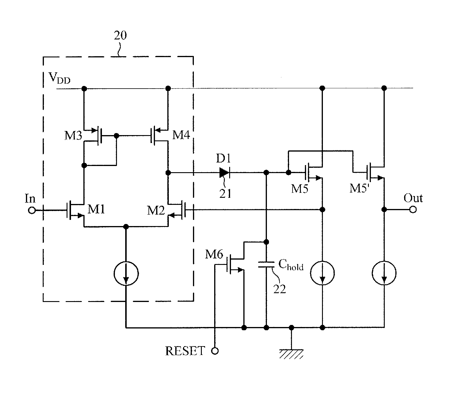
[0014]In order to solve the aforesaid drawbacks of the existing peak detection apparatuses, such as, a long detection time, a degraded resolution, a diode with a large area, and the necessity of supporting the high-frequency diode processing, the following description provides a signal peak detector using a charge

Problems solved by technology

The aforementioned peak detectors are advantageous in terms of stability, but have limitations in application to technologies (e.g., NG-PON2) that relate to prompt detection of signal peak values with a faster response time.
Hence, a correct peak value of the input signal cannot

Method used


Image

  • Peak detector using charge pump and burst-mode transimpedance amplifier
  • Peak detector using charge pump and burst-mode transimpedance amplifier
  • Peak detector using charge pump and burst-mode transimpedance amplifier

Examples


Embodiment Construction

[0031]The following description is provided to assist the reader in gaining a comprehensive understanding of the methods, apparatuses, and / or systems described herein. Accordingly, various changes, modifications, and equivalents of the methods, apparatuses, and / or systems described herein will be suggested to those of ordinary skill in the art. Also, descriptions of well-known functions and constructions may be omitted for increased clarity and conciseness.

[0032]FIG. 2 is a diagram illustrating a configuration of a signal peak detector using a charge pump according to an exemplary embodiment.

[0033]Referring to FIG. 2, the signal peak detector using a charge pump includes a differential amplifier 110, a replica amplifier 120, a capacitor C2130, a mirror current source portion 140, and a current control logic 150. Also, the signal peak detector further includes a low pass filter (LPF) 160 and a reset circuit 170.

[0034]The differential amplifier 110 generates a positive output voltage ...


PUM


Abstract

A peak detector using a charge pump is provided. The peak detector includes a differential amplifier configured to receive an input signal to be detected through an input node and amplify the received signal; a current control logic configured to create two or more current control signals by comparing a signal output from the differential amplifier with two or more reference voltages; a mirror current source portion comprising two or more mirror current sources configured to be driven respectively by the current control signals from the current control logic; a capacitor configured to be charged or discharged by currents output from the mirror current sources; and a reset circuit configured to reset a voltage of the capacitor.

Description

CROSS-REFERENCE TO RELATED APPLICATION(S)[0001]This application claims priority from Korean Patent Application No. 10-2014-0147743, filed on Oct. 28, 2014, in the Korean Intellectual Property Office, the disclosure of which is incorporated herein by reference in its entirety.BACKGROUND[0002]1. Field[0003]The following description relates to a signal level detector used in an electronic circuit, and more particularly, to a peak detector and peak detection method for quickly detecting a peak value of a signal.[0004]Also, the following description discloses a method, associated with a photoelectric amplifier, for processing a signal with low distortion by quickly and stably detecting a signal intensity of burst data and actively controlling a gain of the signal.[0005]2. Description of the Related Art[0006]Signal amplitude and strength detection is a technology that is essential for detecting or recovering data, without errors, in response to a wide range of changes in strength of input...

Claims


Application Information

Patent Timeline
IPC IPC(8): H03K5/1532H03F3/45G01R19/04H03G3/30
CPCH03K5/1532H03G3/30H03F2203/45182G01R19/04H03F2203/45684H03F3/45179H03F3/45183H03F3/45475H03F3/45968H03F2200/435H03F2200/453H03F2203/45138H03F2203/45212H03G3/3084
Inventor KIM, YOUNG HOJUNG, EUI SUK
Owner ELECTRONICS & TELECOMM RES INST
Why Eureka
Try Eureka