[0014] A first aspect of the present invention is a highly parallel data
bus architecture for transferring n different patterns stored in n memory arrays into an image transducer. The symbol n represents an integer equal to or greater than 2. The n different patterns are combined so that the averaged result of 2n−1 partial exposures of the n different patterns is an image having a line placement accuracy of the image transducer pixel size divided by 2n−1. Each
memory array contains a slightly different version of the pattern. For a visual image that might contain about 2 million pixels and require refreshment 30 times a second, the transfer of data from the n memories could be done in serial fashion for values of n as large as 4. However, a value of n=4 improves the line edge placement accuracy by a factor of 15, which, with conventional means, would require 225 times more pixels in the image transducer to obtain the same line edge placement accuracy. This improvement requires the transmission and storage of 4 pictures having coarse resolution. Thus the overall improvement in
data transmission and storage is 225 / 4=56.25 for a value of n=4. This is a substantial improvement, making the technique of the present invention useful when it is desired that an image having high edge placement accuracy be transmitted efficiently over a channel with limited bandwidth or be displayed with an image transducer having relatively coarse pixel sizes.
[0016] In most lithography applications the combination of very high line edge placement accuracy, relatively large picture area (
field size), and high picture repetition rate requires a very efficient means of storing, transferring and displaying data. For example, a modern state-of-the-art lithography system might require a line edge position accuracy of 5 nm over a 22 mm by 22 mm field at a rate of 2 fields per second. Using a 5 nm by 5 nm pixel size would require a
data rate of 3.87×1013 pixels per second. This can be contrasted with using an image transducer pixel size that corresponds to ½ or ⅓ of the minimum feature size and then using multiple partial exposures of a few, coarse-resolution pictures to obtain the required line edge placement resolution. For example, a pixel size corresponding to 50 nm by 50 nm would provide 100 nm minimum feature sizes. Judicious use of 5 patterns would provide a line edge placement resolution of 50 nm / (25−1)=50 nm / 31=1.6 nm. This reduces the data volume for a complete image by 20 times and reduces the number of pixels required in the image transducer 100-fold.
[0018] An aspect of the present invention is a
computer architecture for facilitating the transfer of data to accomplish multiple-
exposure imaging or printing. The architecture includes n memory arrays, where the integer n is equal to or greater than 2, and where each
memory array is capable of storing a low-resolution pattern, all or part of which is used to form the pattern segment formed on the image transducer. The n patterns are preferably all slightly different versions of a single pattern and can be used to generate 2n−1 patterns, each corresponding to the 2n−1 partial exposures used to obtain a complete
exposure of a pattern element. A parallel data
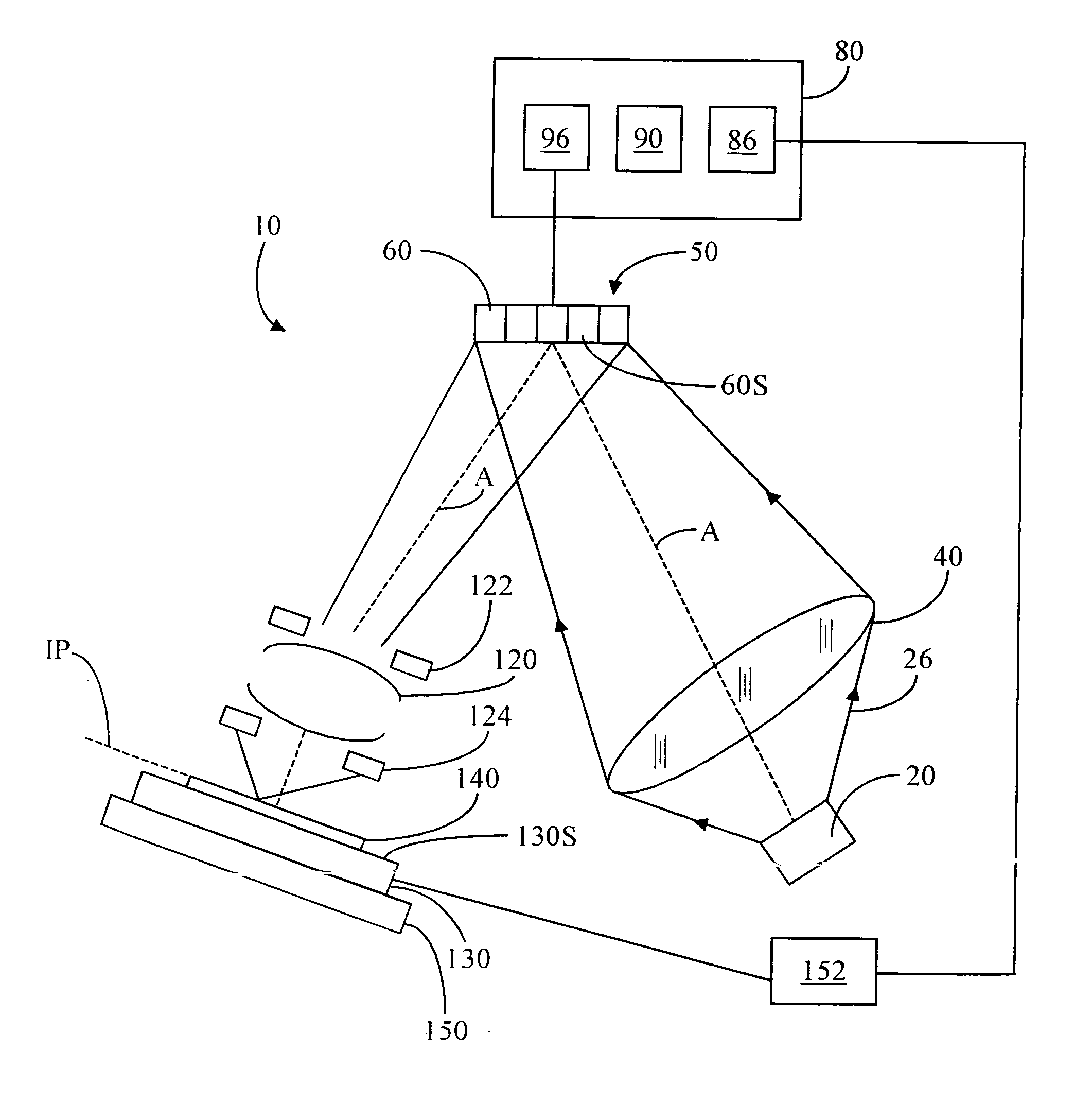
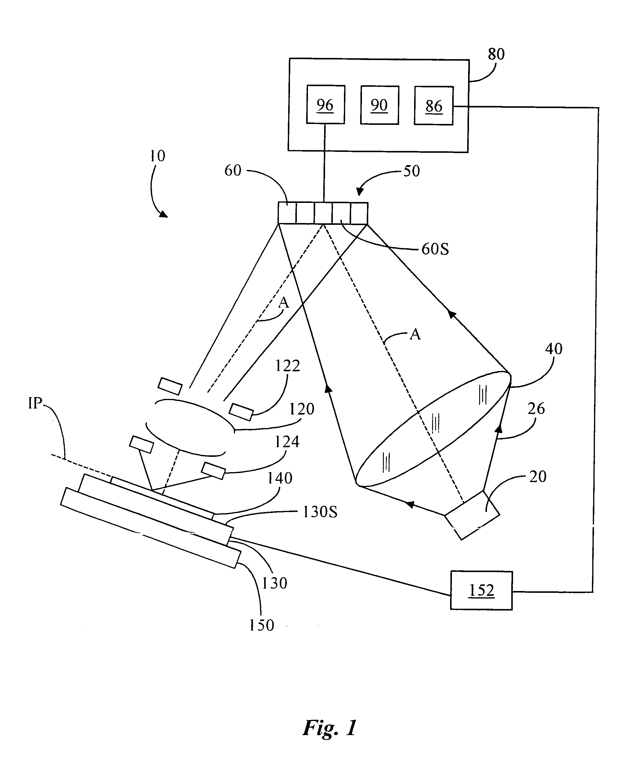
bus electrically connects the n memory arrays to an image transducer
memory array, and to one or more data
bus switches determine which memory array is connected to the
associated image transducer. A
memory control unit is electrically connected to the n memory arrays and the data bus switches. The
memory control unit is programmed differently depending on whether or not the partial exposures of the different patterns are combined statically, such as in a visual display or a step-and-repeat lithography application, or dynamically in a scanning lithography application. In a static application the pictures stored in memory are displayed sequentially, and are combined by the integrating properties of the eye or by partial exposures of a
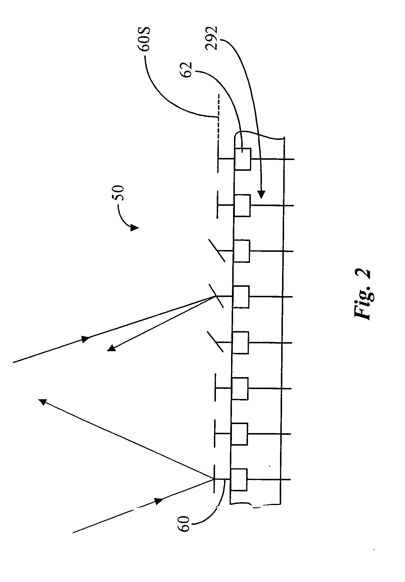
resist film. In a scanning application the
memory control unit is programmed such that 2n−1 columns of pattern data stored in the n memory arrays are sequentially transferred to the 2n−1
memory cell columns of the image transducer memory array between clocking cycles. In this case each picture composed on the image transducer array contains picture elements from each one of the n memory arrays. Each pattern element traverses the image transducer in 2n−1 steps and is exposed with a series of 2n−1
radiation pulses. In the resulting 2n−1 partial exposures, every pattern element is completely exposed. Where necessary, such as in most lithography applications, a highly parallel date transfer architecture can be used to allow for the quick transfer of large amounts of pattern data to the image transducer memory array when forming an image with the image transducer.

