Angular velocity sensor and angular velocity sensing device

Active Publication Date: 2009-07-02
TDK CORPARATION
View PDF1 Cites 7 Cited by
  • Summary
  • Abstract
  • Description
  • Claims
  • Application Information

AI Technical Summary

Benefits of technology

[0007]Also, in Japanese Unexamined Patent Publication No. 2005-106481 and Japanese Patent No. 3734955, a pair of detection arms are provided on both sides of a fixed section or on both sides of a drive arm, and this enables elimination of acceleration component received in the lateral direction. However, in Japanese Unexamined Patent Publication No. 2005-106481, the drive arm and the detection arm are coupled with the fixed section in between so that a complicated mechanism is necessarily provided in the fixed section so as to efficiently transmit a distortion generated by Coriolis force, to the detection arm through the fixed section. Thus, the fixed section is not easily fixed. On the other hand, in Japanese Patent No. 3734955, because the drive arm and the detection arm are directly coupled without the fixed section in between, although the complicated mechanism is not provided in the fixed section, the distortion generated by the Coriolis force can be efficiently transmitted to the detection arm. However, because respective both ends of the drive arm and the detection arm are fixed to the fixed section, the drive arm and the detection arm are hardly vibrated and there is a possibility that sensitivity of a sensor is reduced.
[0026]In the case that the second fixed section fixed on the second support surface is provided, and the middle point of the extending length of the first vibration arm is coupled to the second fixed section, it means that the second fixed section is coupled to a node of the vibration (standing wave) generated in the first vibration arm due to the Coriolis force; thereby unnecessary vibrations of the first vibration arm are suppressed without disturbing the vibrations generated in the first vibration arm due to the Coriolis force.

Problems solved by technology

Hei-8-128833, Japanese Unexamined Patent Publication No. 2004-333460, and Japanese Patent No. 3694160, when the angular velocity sensor receives acceleration in a lateral direction (a direction orthogonal to the longitudinal direction in a horizontal plane), it is difficult to distinguish whether vibrations of a detection arm are generated due to the angular velocity by rotation of the object, or due to the acceleration in the lateral direction.
Thus, the fixed section is not easily fixed.

Method used


Image

  • Angular velocity sensor and angular velocity sensing device
  • Angular velocity sensor and angular velocity sensing device
  • Angular velocity sensor and angular velocity sensing device

Examples


first embodiment

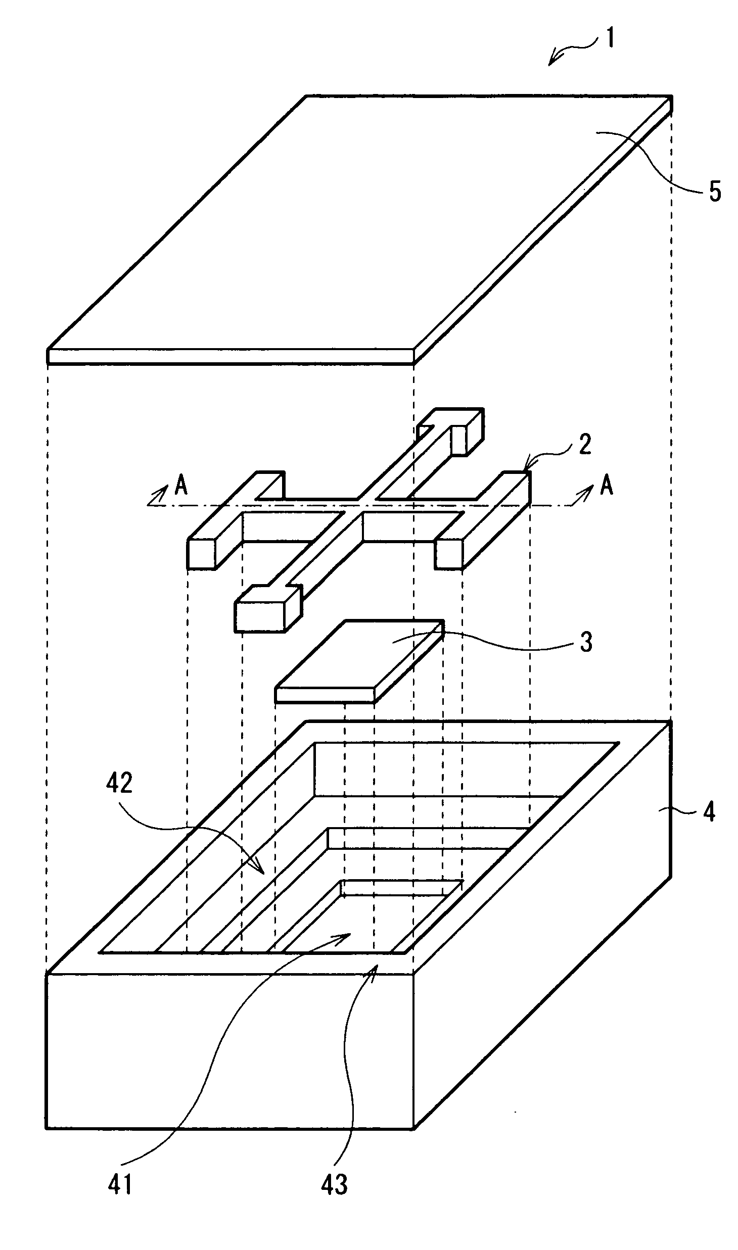
[0045]A configuration of an angular velocity sensing device 1 according to a first embodiment of the present invention will be described in the following. FIG. 1 is an exploded perspective view showing an internal configuration of the angular velocity sensing device 1 according to the first embodiment. FIG. 2 is a cross-sectional view showing a cross-sectional configuration as viewed from arrow A-A of the angular velocity sensing device 1.

[0046]The angular velocity sensing device 1 includes an angular velocity sensor 2 and an integrated circuit 3 in an internal space G (refer to FIG. 2) formed by a case 4 and an upper cover section 5 stacked with each other.

[0047]As will be described later, the integrated circuit 3 transmits a drive signal to each of piezoelectric elements provided on each of drive arms of the angular velocity sensor 2, and receives a detection signal outputted from each of the piezoelectric elements provided on each of detection arms of the angular velocity sensor ...

second embodiment

Modification of Second Embodiment

[0089]In the second embodiment, a middle point 21C of a detection arm 21 is not coupled to a fixed section 20, and thus can be displaced relatively freely. However, as shown in FIGS. 11 and 12, in the condition that one of two pairs of upper drive arms 22 and lower drive arms 23 are coupled to a quarter divided portion 21D in an extending direction of the detection arm 21 and the other of the two pairs of upper drive arms 22 and lower drive arms 23 are coupled to a quarter divided portion 21E in the extending direction of the detection arm 21, using piezoelectric elements 22A, 22B, 23A, and 23B, one of the two pairs of upper drive arms 22 and lower drive arms 23 are driven in the same phase to each other and the other of the two pairs of upper drive arms 22 and lower drive arms 23 are driven in the same phase to each other, and further one of the two pairs of upper drive arms 22 and lower drive arms 23 are vibrated in the phase opposite to the other ...


PUM


Abstract

Provided is a horizontally located sensitive angular velocity sensor capable of easily eliminating influence of acceleration in a lateral direction and whose fixed section is easily fixed. The angular velocity sensor includes a pair of fixed sections fixed on a top of an sensor support section of a case, a detection arm extending along a plane parallel to the sensor support section, and a pair of upper drive arm and lower drive arm extending along the plane parallel to the sensor support section and extending in a direction opposite to each other so as to intersect an extending direction of the detection arm.

Description

CROSS REFERENCES TO RELATED APPLICATIONS[0001]The present invention contains subject matter related to Japanese Patent Application JP 2007-091270 filed in the Japanese Patent Office on Mar. 30, 2007, the entire contents of which being incorporated herein by reference.BACKGROUND OF THE INVENTION[0002]1. Field of the Invention[0003]The present invention relates to an angular velocity sensor detecting an angular velocity of an object and an angular velocity sensing device provided with such an angular velocity sensor.[0004]2. Description of the Related Art[0005]Angular velocity sensors have been used in technique autonomously controlling postures of ships, airplanes, rockets and the like. Recently, the angular velocity sensors have been equipped on small electronic devices such as car navigation systems, digital cameras, video cameras, cell-phones and the like. With that trend, miniaturization and low profile (thinning) of the angular velocity sensors are further demanded. Instead of a...

Claims


Application Information

Patent Timeline
IPC IPC(8): G01C19/56G01C19/5607G01C19/5621H01L41/08H01L41/187
CPCG01C19/5607H01L41/08G01C19/5642H10N30/00
InventorNOGUCHI, TAKAOTOCHI, KENICHIUNNO, KENNAMIKAWA, TATSUO
OwnerTDK CORPARATION