Telescoping wing and airfoil control mechanism

a control mechanism and wing technology, applied in the direction of fuselages, transportation and packaging, spares/stringers, etc., can solve the problems of lack of overlap between adjacent adjacents, add weight and complexity to aircraft, etc., and achieve the effect of simple design and operation, light moving structure, and low weigh

Inactive Publication Date: 2009-07-02
BOUSFIELD SAMUEL HALL
View PDF6 Cites 53 Cited by
  • Summary
  • Abstract
  • Description
  • Claims
  • Application Information

AI Technical Summary

Benefits of technology

[0009]The present invention provides a means to physically retract or extend airfoils relative to a vehicle body, while keeping the moving structure light and simple in design and operation. One aspect of the invention provides for the extending mechanism to also be utilized for wing warp control, providing a means to direct the flight path as well. Maintaining wing extension during flight is an added feature of the present invention, and is done by utilizing aerodynamic forces rather than structure, to keep weight to a minimum. Special wing panel structure is described as part of the present invention. This wing panel structure maximizes strength of the hollow wing panels described as part of the moving structure, and allows for hollow sections to retain adequate stiffness, and yet be lightweight.

Problems solved by technology

While of obvious benefit, these latter wing extension devices add weight and complexity to aircraft that in the real world depend upon low weight and simplicity to operate.
The limitation of this design appears to be the lack of overlap between adjacent spar sections when fully extended, which dictates heavier spar sections and a heavy wing design.

Method used


Image

  • Telescoping wing and airfoil control mechanism
  • Telescoping wing and airfoil control mechanism
  • Telescoping wing and airfoil control mechanism

Examples


Embodiment Construction

[0028]Reference will now be made in detail to the preferred embodiment of the invention, which is illustrated in the accompanying drawings. While the invention will be described in conjunction with the preferred embodiment, it will be understood that it is not intended to limit the invention to this embodiment. On the contrary, the invention is intended to cover alternatives, modifications and equivalents, which may be included within the spirit and scope of the invention as defined by the appended claims.

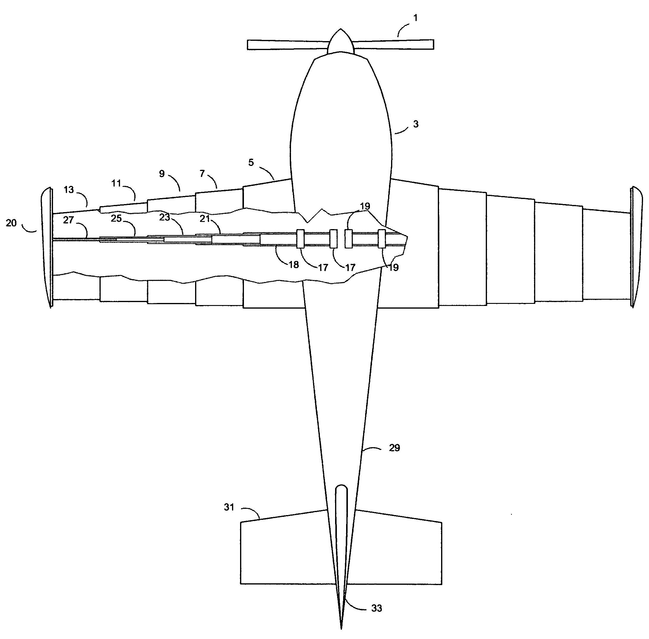
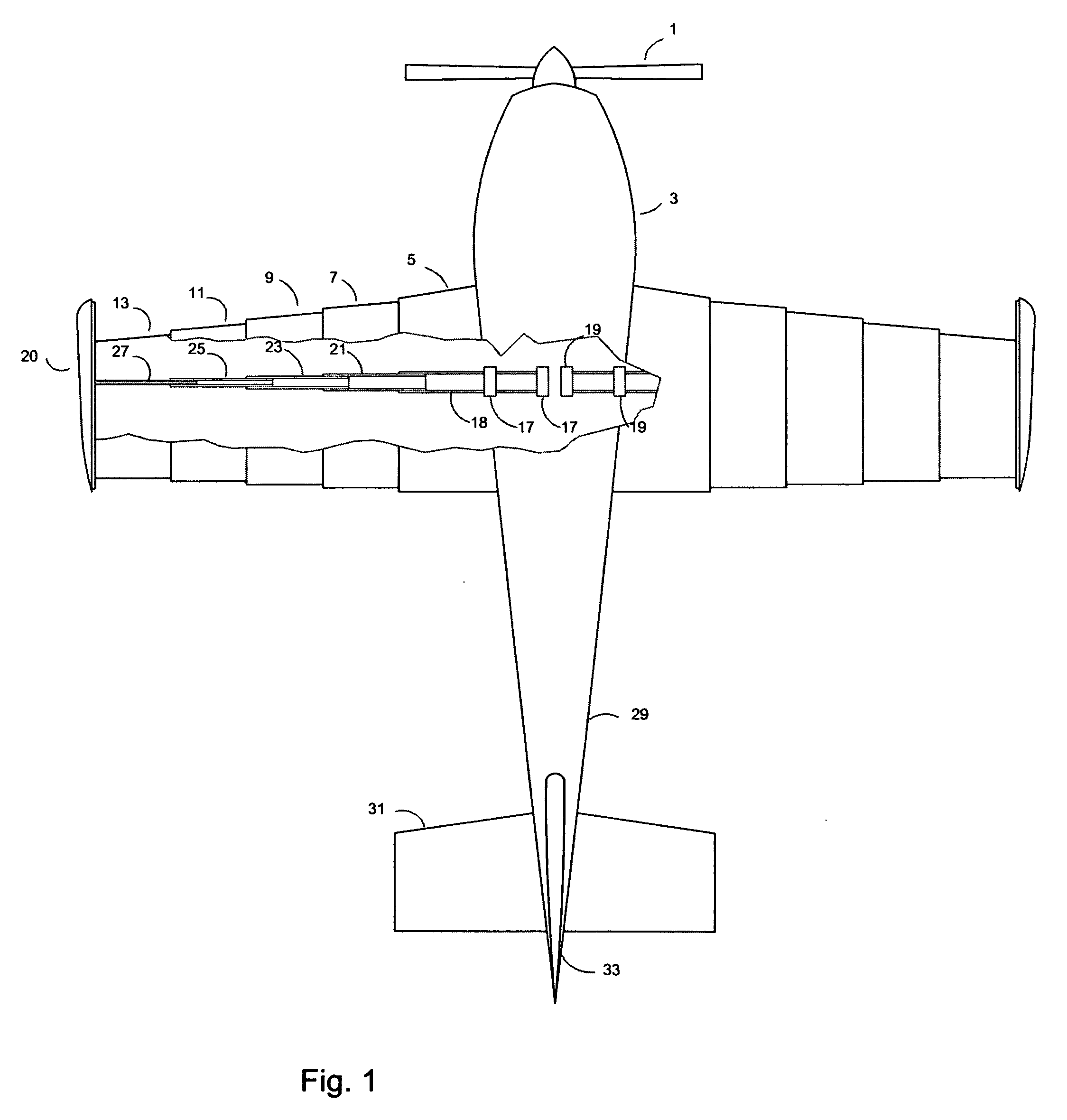
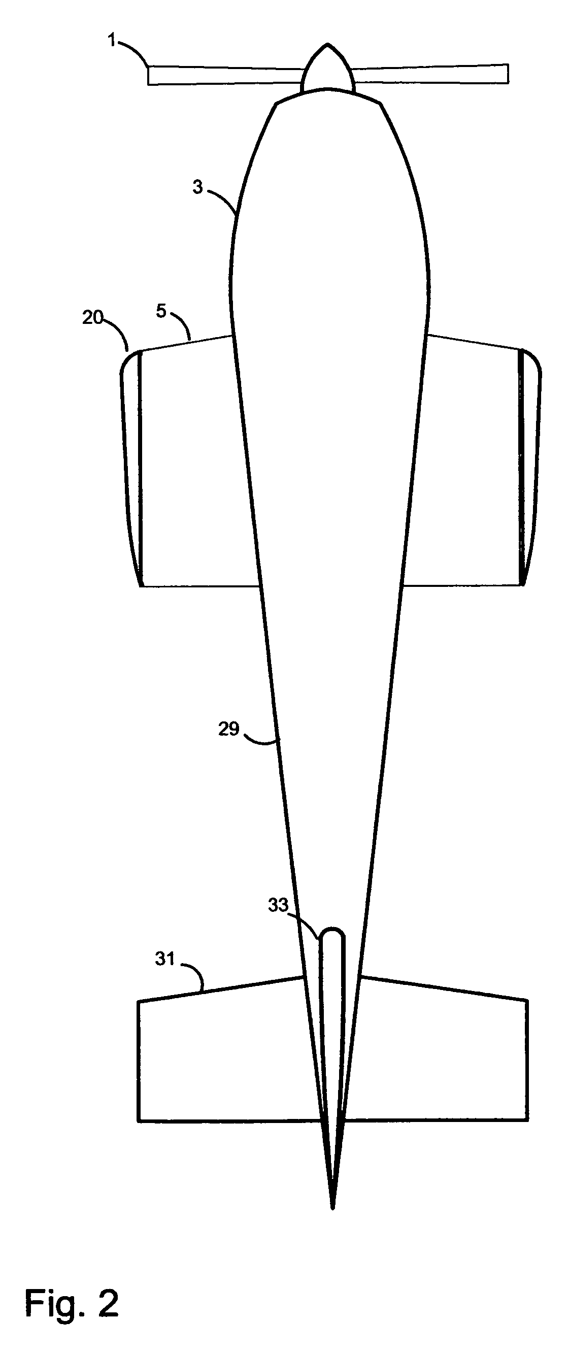
[0029]The present invention, in a general sense, is shown FIG. 1&FIG. 2. FIG. 1 is a cut-away view of the preferred embodiment of the assembly on an aircraft with wings extended. The view shows a propeller (1), attached to the nose of an aircraft fuselage (3), said fuselage having a hollow wing root (5). Also shown are hollow wing panels (7, 9, 11, 13), which are sized to slide into each other toward said wing root, guided by retractable wing spars (21, 23, 25, 27). At the end of s...


PUM


Abstract

This invention relates generally to a collapsible, nesting wing structure with or without wing warp flight control. The invention also incorporates means to maintain wing extension during flight, methods of wing construction for nesting collapsible wings, and control surfaces for collapsible wings.

Description

CROSS REFERENCE TO RELATED APPLICATIONS[0001]N / ASTATEMENT REGARDING FEDERALLY SPONSORED RESEARCH AND DEVELOPMENT[0002]No State or Federal funds were used for the research and development of this invention.REFERENCE TO SEQUENCE LISTING, A TABLE, OR A COMPUTER PROGRAM LISTING COMPACT DISC APPENDIX[0003]N / ABACKGROUND OF THE INVENTION[0004]Differing aircraft wing designs are as old as flight itself, or perhaps older, considering the many designs penned by Michelangelo. Specifically, the Wright Brothers airplane in what is considered Man's first powered flight utilized wing warping for flight control. As ambition loaded wings more heavily in the years following, a fixed wing and movable control surfaces became the control means of choice. This trend has maintained until present day. Recently, NASA, among others, began exploring wing warp control for use in drones or unmanned air vehicles.[0005]One such investigation is detailed in American Institute of Aeronautics and Astronautics (AIAA)...

Claims


Application Information

Patent Timeline
Patent Type & Authority Applications(United States)
IPC IPC(8): B64C3/54B64C3/52B64C3/18
CPCB64C3/18B64C2201/102B64C3/56B64C3/52B64U30/12
Inventor BOUSFIELD, SAMUEL HALL
Owner BOUSFIELD SAMUEL HALL
Why Eureka
Try Eureka