Balloon-in-balloon cervical canal dilator

a cervical canal and balloon technology, applied in balloon catheters, surgery, other medical devices, etc., can solve the problems of insufficient cervical balloon design, damage to the uterus, and failure to dilate the full length of the cervix, so as to reduce the diameter of the catheter for insertion

Inactive Publication Date: 2006-11-30
OS TECH
View PDF0 Cites 24 Cited by
  • Summary
  • Abstract
  • Description
  • Claims
  • Application Information

AI Technical Summary

Benefits of technology

[0020] The external balloon would need to be placed over the internal balloon after the internal balloon is attached to the catheter body. In previous use, a non-compliant balloon is molded to have edges which are tapered to have internal diameters that match the external diameter of the catheter shaft to which they are to be attached. In order to be placed over another balloon, this design would require that one edge of the external balloon be tapered to a diameter wide enough to be passed over the affixed internal balloon. In order to effect a seal at the balloon edge with the wider taper, the surface of the catheter will need to be modified to create a wider edge to which to bond the outer balloon. This could be accomplished by affixing a wider tube which has an inner diameter equal to the outer diameter of the catheter shaft and an outer diameter equal to the inner diameter of the balloon taper; this tube would preferable be made of inelastic material to provide the bond strength required to withstand inflation pressures of 150 psi or higher.
[0021] If the inner balloon is made of inelastic material, elastic bands or breakaway ties could be used to hold the deflated balloon in a folded manner while the outer balloon is placed and folded over it. This will minimize the diameter of the catheter for insertion.

Problems solved by technology

Prior inelastic balloon designs for cervical dilation have been inadequate due to the lack of visualization of the cervical canal to assist the user in placing the catheter.
For this reason, a single balloon for dilation, similar to that used in angioplasty, is ineffective, resulting in insertion of the catheter too far, causing damage to the uterus, or not inserting the catheter far enough, causing failure to dilate the full length of the cervix.
This problem is exacerbated by the uneven resistance along the length of the cervical canal.
If dilation is attempted with a catheter using a single non-compliant (non-elastic) balloon, similar to a traditional angioplasty catheter, and the balloon is not properly positioned with the distal tip well beyond the inner os, the higher resistance at the inner os, the portion of the cervix closest to the uterus, will push the tapered balloon tip outward, resulting in incomplete dilation.
Several alternative designs to correct this deficiency do not adequately address the issues surrounding dilation of the inner os.
These alternatives will potentially result in insufficient dilation of some portion of the cervix or over dilation of a portion of the cervix, risking damage to the cervix that could lead to cervical incompetence later.
The failing of this potential design is that the distal tip of the catheter must be located within the body of the uterus.
Use of a fixed-length balloon without means of distal anchor will not work, since it will not be possible to maintain sufficient forward pressure on a flexible catheter across the vaginal canal to prevent the cervix from ejecting the balloon.
Because inelastic balloons require a taper in order to be folded and a space to be glued to the catheter body, there will be a gap between the two balloons, potentially causing the distal portion of the cervical canal to not be adequately dilated.
If the catheter is alternately pulled so an ellipsoidal balloon is located at the point of the inner os, the ellipsoidal balloon may over dilate a portion of the cervix, causing damage such as tearing or cervical incompetence, with resultant fetal loss.
This embodiment poses a potential problem in that the wider portion of the ellipsoidal section of the balloon could be positioned within the cervix causing over dilation and resultant damage.

Method used


Image

  • Balloon-in-balloon cervical canal dilator
  • Balloon-in-balloon cervical canal dilator
  • Balloon-in-balloon cervical canal dilator

Examples


Embodiment Construction

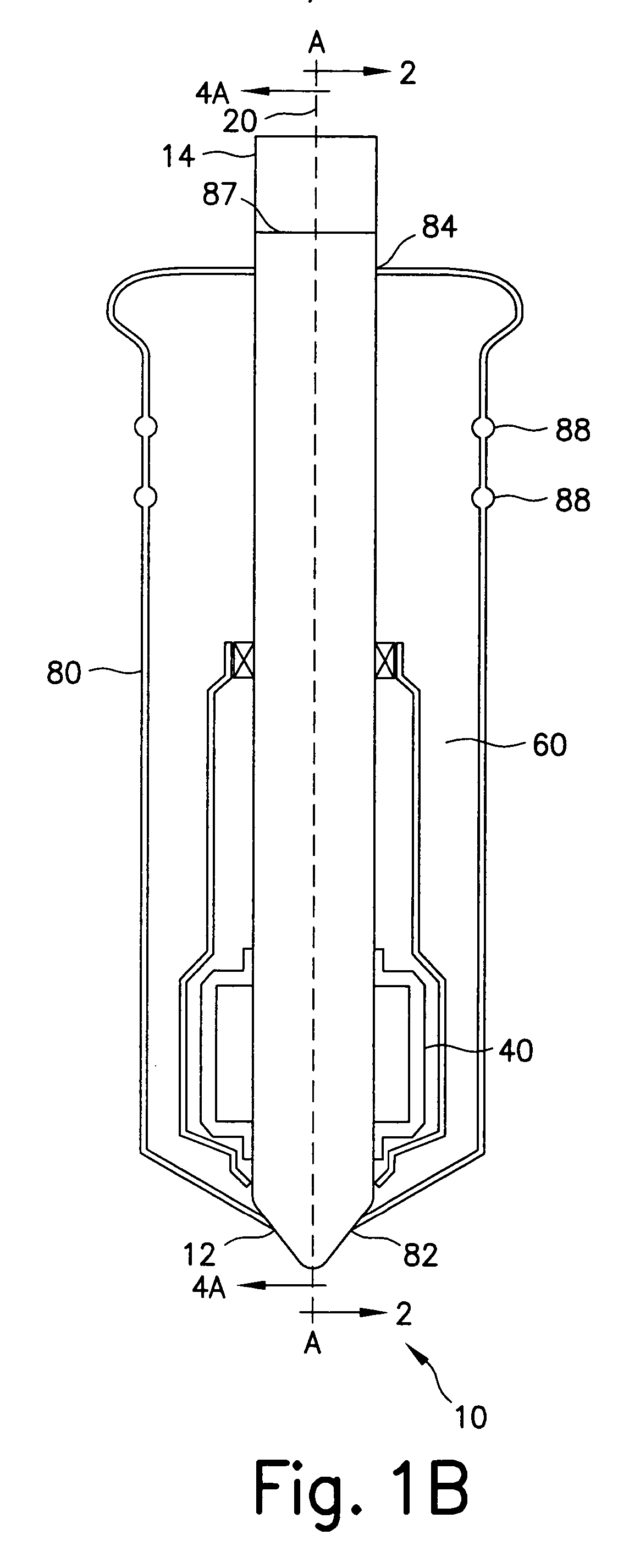
[0036] Referring now in specific detail to the drawings in which like referenced numerals identify similar or identical elements throughout the several views, and initially to FIG. 1A, a novel cervical canal dilator assembly 10 is shown having a shaft 20, a first inflatable member 40, a second inflatable member 60 and a control system 90 (see FIG. 3A). Cervical canal dilator assembly 10, hereinafter referred to as “dilator 10” has a distal end 12 and a proximal end 14 defining a longitudinal axis-A.

[0037] Referring now to FIGS. 1A, 1B, 2, 3A, 3B, 3C, 4A and 4B, shaft 20 has a distal end portion 22 and a proximal end portion 24 aligned with first longitudinal axis-A. Distal end portion 22 includes a tip 21 having a solid circular base 21a and a tapered or conical outer shape. Tip 21 is advantageously shaped for ease of insertion into the cervical canal of the patient. Shaft 20 has a cylindrical outer surface 32. Proximal end portion 24 is connected with control system 90.

[0038] Sha...


PUM


Abstract

A cervical canal dilator having an elongate tubular shaft that defines at least two internal lumens that are juxtaposed to a longitudinal axis. A first inflatable member is positioned on the outer surface of the shaft and is in communication with the first lumen. While a second inflatable member is also positioned on the outer surface of the shaft. The second inflatable, however, is longer than and completely covers the first inflatable member. Additionally, the second member is fabricated of a non-elastic material that limits the inflation of the second member to a predetermined maximum diameter of inflation. The device, also, has a control system which controls the fluids and/or gases that enter the lumens.

Description

THE FIELD OF THE INVENTION [0001] This particular invention generally pertains to a cervical canal dilator having an elongate tubular shaft that defines at least two internal lumens which are juxtaposed to a longitudinal axis. More specifically, it is directed to a dilator having a first inflatable member and a second inflatable member wherein the second member is longer than and completely covers the first inflatable member. BACKGROUND OF THE INVENTION [0002] Prior inelastic balloon designs for cervical dilation have been inadequate due to the lack of visualization of the cervical canal to assist the user in placing the catheter. This differs from the use of inelastic balloons in angioplasty; when balloons are used in angioplasty the catheter placement is visualized with fluoroscopy. For this reason, a single balloon for dilation, similar to that used in angioplasty, is ineffective, resulting in insertion of the catheter too far, causing damage to the uterus, or not inserting the c...

Claims


Application Information

Patent Timeline
Patent Type & Authority Applications(United States)
IPC IPC(8): A61M29/00
CPCA61M29/02A61M31/00A61M2025/1013
Inventor REED, DAVIDFOLTZ, JONATHAN
Owner OS TECH
Why Eureka
Try Eureka