Device and method for capturing speckles

a technology of speckles and devices, applied in measurement devices, instruments, computing, etc., can solve problems such as speckle patterns, and achieve the effects of improving speckle pattern imaging configuration and techniques, improving accuracy, and more certainty

Inactive Publication Date: 2007-06-21
NAT CHUNG SHAN INST SCI & TECH
View PDF5 Cites 29 Cited by
  • Summary
  • Abstract
  • Description
  • Claims
  • Application Information

AI Technical Summary

Benefits of technology

[0011] This invention relates to the application of relative motion detection utilizing a coherent light source and improved speckle pattern imaging configuration and techniques. The purpose of this invention is to provide a device and method for controlling and measuring speckle images in displacement monitory applications. When the scattered lights bouncing off a surface illuminated by a beam of coherent light source are allowed to pass through a small light restrictive aperture, diffraction phenomenon occurs. The diffracted optical waves originated from adjacent lights passing through the aperture interfere with one another to produce larger speckle than that without small aperture. This size-enlargement effect makes it possible for the detector array to register each speckle spot with more certainty and determine the movement of the pattern with better accuracy. The relative motion between the surface and the beam source—detector assembly can be calculated by comparing the position changes of speckle pattern from consecutive picture frames taken by the detector unit.

Problems solved by technology

The diffracted lights interfere with one another to produce a speckle pattern.

Method used


Image

  • Device and method for capturing speckles
  • Device and method for capturing speckles
  • Device and method for capturing speckles

Examples


Embodiment Construction

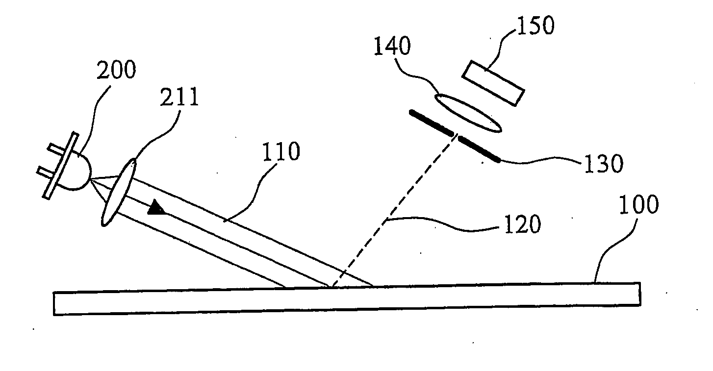
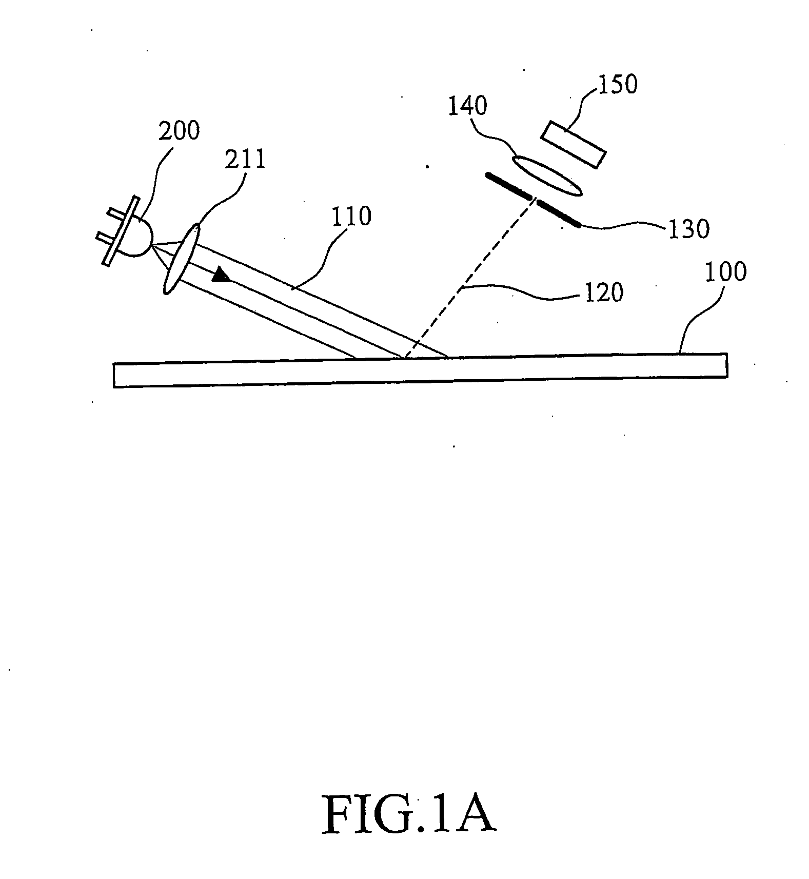
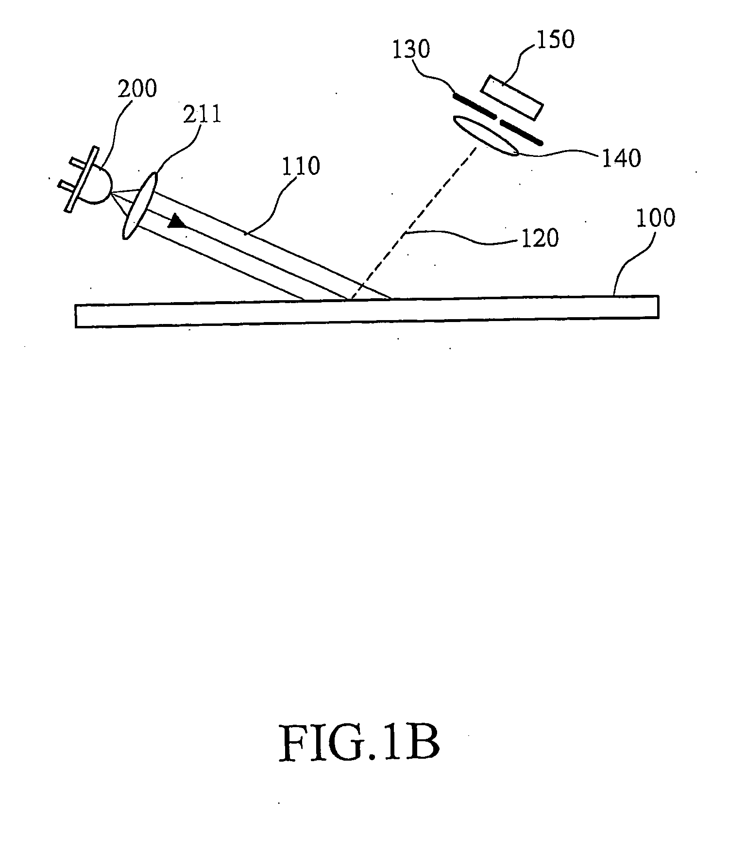
[0032] The system structure of the present invention is illustrated in FIG. 1A. When a light emits onto a surface 100, the properties of the reflected lights are determined by the roughness of the surface 100. The smoother the surface 100 is, the more mirror-like the surface 100 will be. In that case, the incident light 110 is almost totally reflected, with the reflected energy nearly the same as the incident energy. The rougher the surface 100 is, the foggier the surface 100 will be. After projecting onto the rough surface 100, the light is scattered almost in all directions. This is because the surface 100 is so rough that the lights propagate in arbitrary directions due to the scattering effect.

[0033] After the incident light 110 projects onto the surface 100, a lens 140 and an image sensor 150 are used to receive the scattered lights 120. In order to enlarge the speckle, a light restrictive element is disposed in front of the image sensor 150. The light restrictive element is a...


PUM


Abstract

A method and device for capturing speckles are described. A highly coherent light emitted from a light source is used to illuminate a surface and produces scattered lights. The scattered lights pass through a light restrictive element and the diffracted lights produced by this restrictive element interfere with one another to generate a speckle pattern. An image sensor is then used to pick up the speckle pattern to form a speckle image. Therefore, the effects of diffraction and interference and a light restrictive element to enlarge the speckle size and reduce the variation of the speckle pattern during the movement of the imaging device are utilized, so that the speckle pattern can be clearly identified in the image. As a result, the method and device for capturing speckles are fairly stable and sensitive.

Description

BACKGROUND OF THE INVENTION [0001] 1. Field of Invention [0002] The present invention relates to the application of relative motion detection utilizing a coherent light source and improved speckle pattern imaging configuration and technique. [0003] 2. Description of Related Art [0004] Laser is a light source with high coherence. When two highly coherence lights close to each other and the optical path difference (OPD) is less than the coherent length, they will interfere with each other. There are constructive and destructive interferences, where the former produces bright fringes while the latter produces dark fringes. Therefore, the interference between two coherent light beams often produces a pattern with alternating bright and dark fringes. Moreover, the interference is related to the wavelength of the light. When two beams overlap, a destructive interference occurs if the phase difference is half the wavelength, whereas a constructive interference occurs if the phase differenc...

Claims


Application Information

Patent Timeline
Patent Type & Authority Applications(United States)
IPC IPC(8): G01B11/14
CPCG01B11/002G06F3/03543
Inventor HWANG, YI-YUHCHEN, MINGWANG, MAU-RANHUANG, WEN-CHENMA, SHIN-I
Owner NAT CHUNG SHAN INST SCI & TECH
Why Eureka
Try Eureka