
Plasma display panel and method for driving the same

a technology of display panel and display panel, applied in the direction of instruments, static indicating devices, etc., can solve the problems of heterogeneous discharge, low brightness, and difficult to achieve the effect of driving apparatus and driving technique improvemen

Inactive Publication Date: 2005-06-21
SAMSUNG SDI CO LTD
View PDF21 Cites 2 Cited by
  • Summary
  • Abstract
  • Description
  • Claims
  • Application Information

AI Technical Summary

Benefits of technology

[0013]It is another object to provide an apparatus and technique for driving a PDP with no more than one reset pulse voltage being applied for one TV field without a reset step between the respective sub-fields, thereby drastically reducing ineffective light and improving the contrast.
[0014]It is yet another object to provide an apparatus and technique for driving a PDP with a plurality of scan and sustain electrodes being arranged so as to reduce the number of driver IC's for the scan and sustain electrodes, thereby lowering the cost of the PDP.

Problems solved by technology

The ADS driving method is problematic in that the brightness is too low, because the sustain discharge period is shorter than the address period.
In addition, the sustain discharge must be activated again after addressing the whole screen, so that wall charges generated in the discharge cells are heterogeneous due to the elapsed time for the address period, thereby causing a false discharge and a heterogeneous discharge during the sustain discharge period and hence a deterioration of the image quality.
In both the ADS driving method and the AWD driving method, however, the individual sub-fields consist of a reset period, an address period, and a sustain discharge period, and a large amount of ineffective light is generated due to reset and erase pulses in the reset period, resulting in a deterioration of contrast.

Method used


Image

  • Plasma display panel and method for driving the same
  • Plasma display panel and method for driving the same
  • Plasma display panel and method for driving the same

Examples


Embodiment Construction

[0035]In the following detailed description, only the preferred embodiment of the invention has been shown and described, simply by way of illustration of the best mode contemplated by the inventor(s) of carrying out the invention. As will be realized, the invention is capable of modification in various obvious respects, all without departing from the invention. Accordingly, the drawings and description are to be regarded as illustrative in nature, and not restrictive.

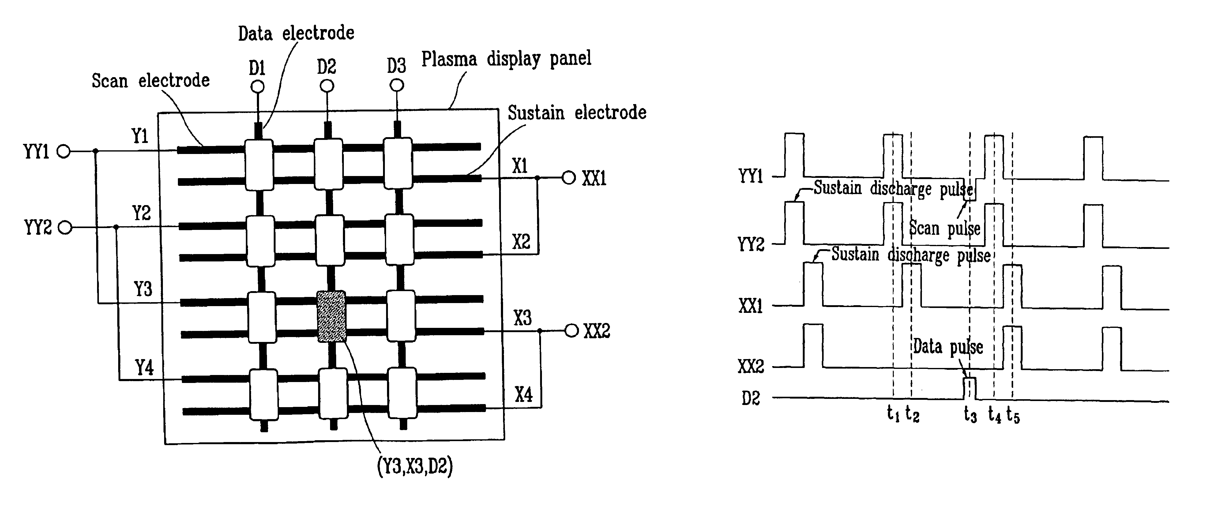
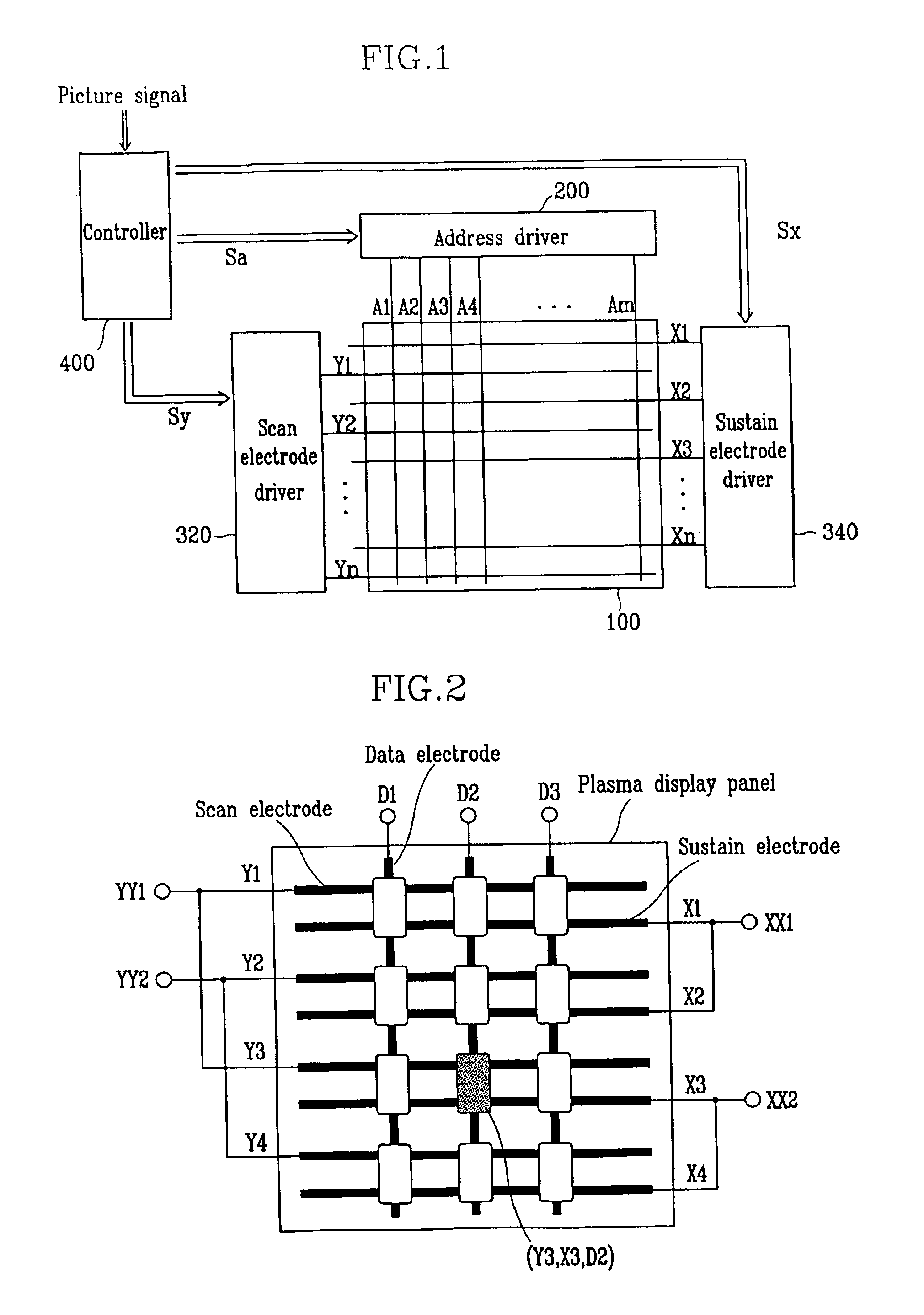
[0036]Hereinafter, a description will be given as to a PDP according to an embodiment of the present invention with reference to FIGS. 1 and 2.

[0037]FIG. 1 is a schematic diagram of the PDP according to the embodiment of the present invention.

[0038]The PDP according to the embodiment of the present invention includes, as shown in FIG. 1, a plasma panel 100, an address driver 200, a scan electrode (Y electrode) driver 320, a sustain electrode (X electrode) driver 340, and a controller 400.

[0039]The plasma panel 100 incl...


PUM


Abstract

A technique for driving a PDP, which includes scan and sustain electrodes arranged in pairs, data electrodes arranged alternately with the scan electrodes, and sub-fields for one TV field to display a multi-gradation, includes applying a reset pulse voltage to the sustain electrodes, applying a first voltage alternately to the scan electrodes and the sustain electrodes to cause a sustain discharge, and after applying a second voltage to the sustain electrodes or removing part of the first voltage applied to the sustain electrodes, applying third and fourth voltages to the scan electrodes and the data electrodes, respectively, before applying the first voltage, to erase wall charges in cells defined by the sustain electrodes, the data electrodes, and the scan electrodes.

Description

CLAIM OF PRIORITY[0001]This application makes reference to, incorporates the same herein, and claims all benefits accruing under 35 U.S.C. §119 from an application for “PLASMA DISPLAY PANEL AND METHOD FOR DRIVING THE SAME” earlier filed in the Korean Intellectual Property Office on Jul. 23, 2002 and there duly assigned Serial No. 2002-43250.BACKGROUND OF THE INVENTION[0002]1. Field of the Invention[0003]The present invention relates to a plasma display panel and a method for driving the same.[0004]2. Description of the Related Art[0005]A plasma display panel (PDP) is a type of display device that has a plurality of discharge tubes arranged in a matrix form, and it selectively makes them radiate to reconstitute picture data input as electrical signals. The driving method of the PDP is classified into a DC (direct current) driving method and an AC (alternating current) driving method, according to whether or not the polarity of the voltage applied to sustain a discharge is changed wit...

Claims


Application Information

Patent Timeline
Patent Type & Authority Patents(United States)
IPC IPC(8): G09G3/10G09G3/04G09G3/28G09G3/288
CPCG09G3/2927G09G3/293G09G3/2942G09G2320/0238G09G2310/0216G09G2310/0218G09G3/296G09G3/291
Inventor KANG, KYOUNG-HOKIM, DAE-GYUMIKOSHIBA, SHIGEOISHII, MAKOTOGOTODA, AKIRAIGARASHI, KIYOSHI
Owner SAMSUNG SDI CO LTD
Learn More