Stent and Method for Manufacturing the Same

a technology of stents and wires, applied in the field of stents, can solve the problems of affecting the quality of products, and the elastic force of other wires, so as to reduce the damage of materials forming prevent the inadvertent dislocation of first and second members from a target place, and increase the elastic force

Inactive Publication Date: 2008-07-10
STANDARD SCI TECH
View PDF17 Cites 28 Cited by
  • Summary
  • Abstract
  • Description
  • Claims
  • Application Information

AI Technical Summary

Benefits of technology

[0015]According to the present invention, a cylindrical stent with big mesh sizes is formed of the first member. After then the second member is crossed the track of the first member in order to form a cylindrical stent with small mesh sizes. Therefore, inadvertent displace of the first and second members from a target place can be prevented, and damages of materials forming of the first and second members are reduced thereby producing qualitative products.
[0016]In addition, according to the present invention, the distal end of the first member is continuously twisted around a part of the first member in order to form the first spirally twisted strut, and the distal end of the second member is continuously twisted around a part of the second member in order to form the second spirally twisted strut. Therefore, the spirally twisted struts increase an elastic force from a center to a radial direction. Also, when the stent is inserted to the lesion, the stent minimizes moving or overlapping to a longitudinal direction thereby the stent may be inserted easily. In addition, the increased elastic force of the stent to the radial direction maintains the stent fixed status at the lesion thereby maximizing the healing effect on a patient by preventing the stent moving from the lesion.
[0017]Also, according to the present invention, the first and second members have a crossed structure when the first and second members meet each other thereby minimizing a diameter of the stent. When the stent has the minimum diameter, the stent has the minimum volume. Therefore, the stent may be inserted easily using the introducer thereby reducing the pain of a patient.

Problems solved by technology

However, during one wire member is woven, the other wire member is left twisted or waved.
Therefore, the wire members may be damaged during the above-described process, thereby being reduced in their elastic force and thus deteriorating the quality of the product.

Method used


Image

  • Stent and Method for Manufacturing the Same
  • Stent and Method for Manufacturing the Same
  • Stent and Method for Manufacturing the Same

Examples


Embodiment Construction

[0021]The present invention will now be described more fully with reference to the accompanying drawings, in which an exemplary embodiment of the invention is shown.

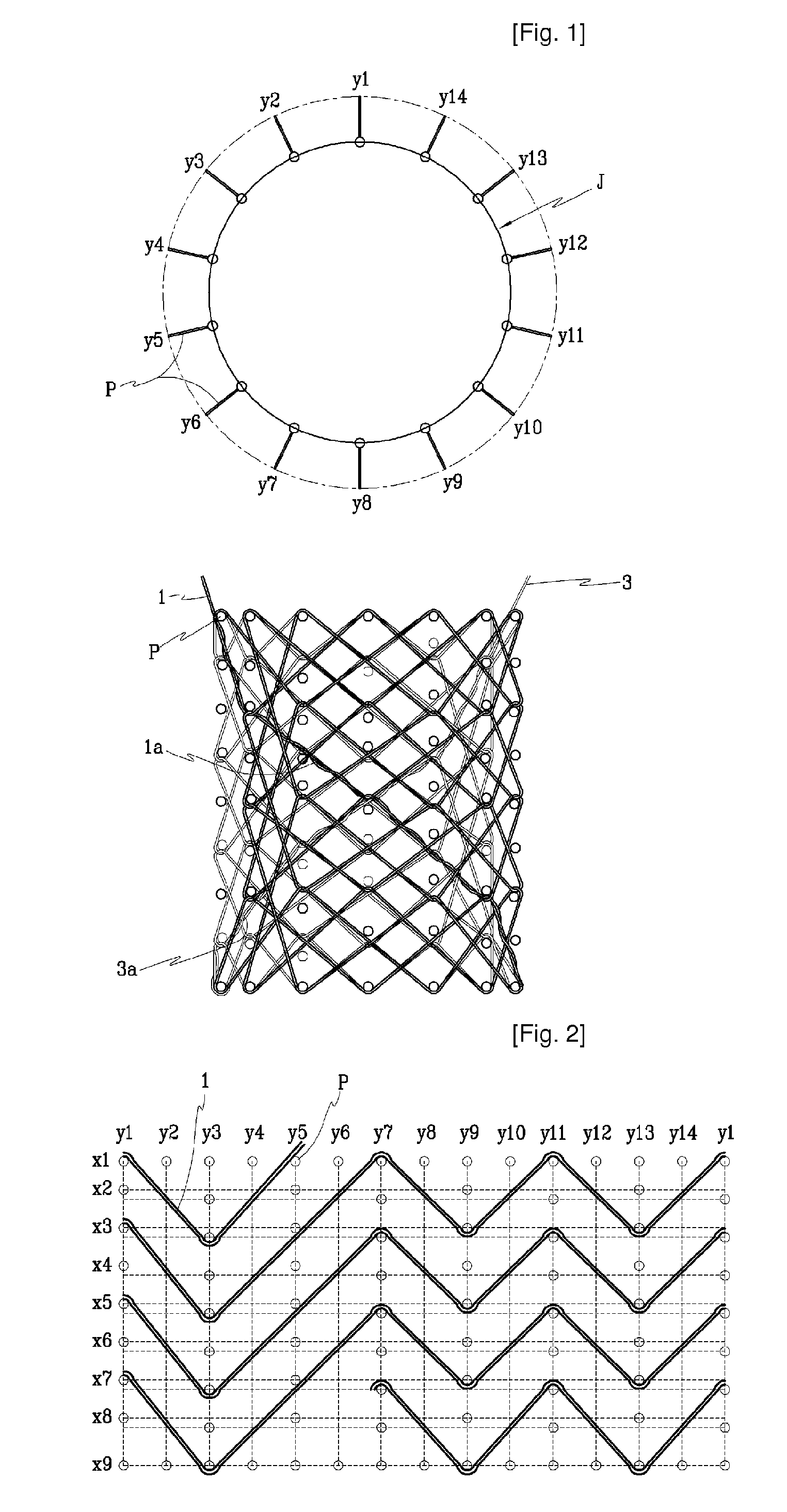
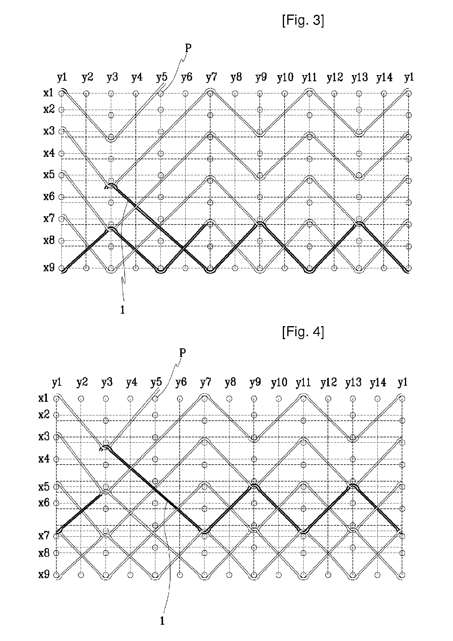
[0022]FIG. 1 is a perspective view of a stent manufactured by a method of the present invention. FIGS. 2 through 14 are views illustrating consecutive processes of manufacturing the stent.

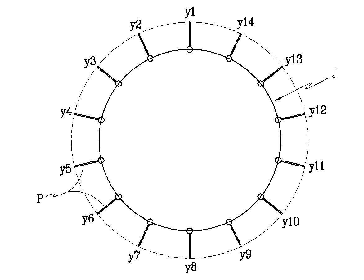
[0023]According to an embodiment of the present invention, a stent is formed of first and second members 1 and 3. FIGS. 2 through 7 are views illustrating a process, in which the cylindrical stent is formed of the first member on a manufacturing frame. FIGS. 8 through 14 are views illustrating a process, in which a fine mesh structure is formed of the second member. The fine mesh structure is formed on the cylindrical stent formed of the first member. The first and second members 1 and 3 may be formed of a wire member, which may be coated in order to be inserted into a lumen or a lesion of a human body for a medical use. Hereinafter, th...


PUM


Abstract

A method of manufacturing a stent includes forming a first cylindrical mesh structure by bending a first member in a zigzag-shape having peaks and valleys and a plurality of turns wound around an outer circumference of a manufacturing frame and forming a second cylindrical mesh structure by bending a second member in a zigzag-shape having peaks and valleys and a plurality of turns wound around an outer circumference of a manufacturing frame, wherein a bending track the second member crosses a bending track of the first member.

Description

TECHNICAL FIELD[0001]The present invention relates to a stent and a method for manufacturing the same, and more particularly, to the stent that is improved in a quality by preventing the damage of a material thereof during a manufacturing process and a method for manufacturing the stent.BACKGROUND ART[0002]Generally, a stent may be inserted into a lumen of a human body, or into a lesion of a blood vessel in order to maintain a passageway of the lumen, or the blood vessel. The stent may be formed of a shape memory alloy such as nitinol maintaining a uniform expansion force at a temperature of the lumen. The stent may be formed in a cylindrical shape woven by wires, and the cylindrical stent may be formed of two thin long members successively woven repeatedly in order to have a good expansion force (elastic force) in a radial direction. That is, a plurality of pins are disposed on a cylindrical manufacturing frame. Distances between the pins are same as each other. The two thin, long ...

Claims


Application Information

Patent Timeline
Patent Type & Authority Applications(United States)
IPC IPC(8): A61F2/06
CPCD10B2509/06A61F2/90A61F2240/001A61F2/82A61F2/89A61F2/86
Inventor AN, SUNG-SOON
Owner STANDARD SCI TECH
Why Eureka
Try Eureka