Locking device for a shielded sub-miniature connection assembly

a sub-miniature connection and locking device technology, applied in the direction of coupling device connection, coupling/disassembly parts engagement/disengagement, electric devices, etc., can solve the problems of premature wear, difficult for users to perform, and all operations of disassembly either in manufacture with a view to repairs or after commissioning prove impossibl

Active Publication Date: 2010-11-30
SOURIAU
View PDF11 Cites 22 Cited by
  • Summary
  • Abstract
  • Description
  • Claims
  • Application Information

AI Technical Summary

Benefits of technology

[0012]According to this embodiment of the invention, the latch additionally comprises an elastic terminal shackle provided at the end resting in the recess in such a way as to improve the mechanical strength of the latch and the recovery of back effects during support on the branches to separate the connectors.
[0015]According to the invention, this arrangement makes it possible to use a movable latch, which is removed during the process of nickel coating of the surface of the molded thermoplastic half-shells, making it possible to avoid placing the latch in the treatment baths.

Problems solved by technology

During manufacture the said means are permanently fixed and the locking of the springs on the pins of the complementary connector necessitates an introduction operation, which is difficult for users to perform.
This latch, which is subjected to surface treatment operations on the housing, comprises an elastic link, which shows over time, premature wear due to frequent manipulations.
According to this technique, all operations of disassembly either in manufacture with a view to repairs or after commissioning prove to be impossible.

Method used


Image

  • Locking device for a shielded sub-miniature connection assembly
  • Locking device for a shielded sub-miniature connection assembly
  • Locking device for a shielded sub-miniature connection assembly

Examples


Embodiment Construction

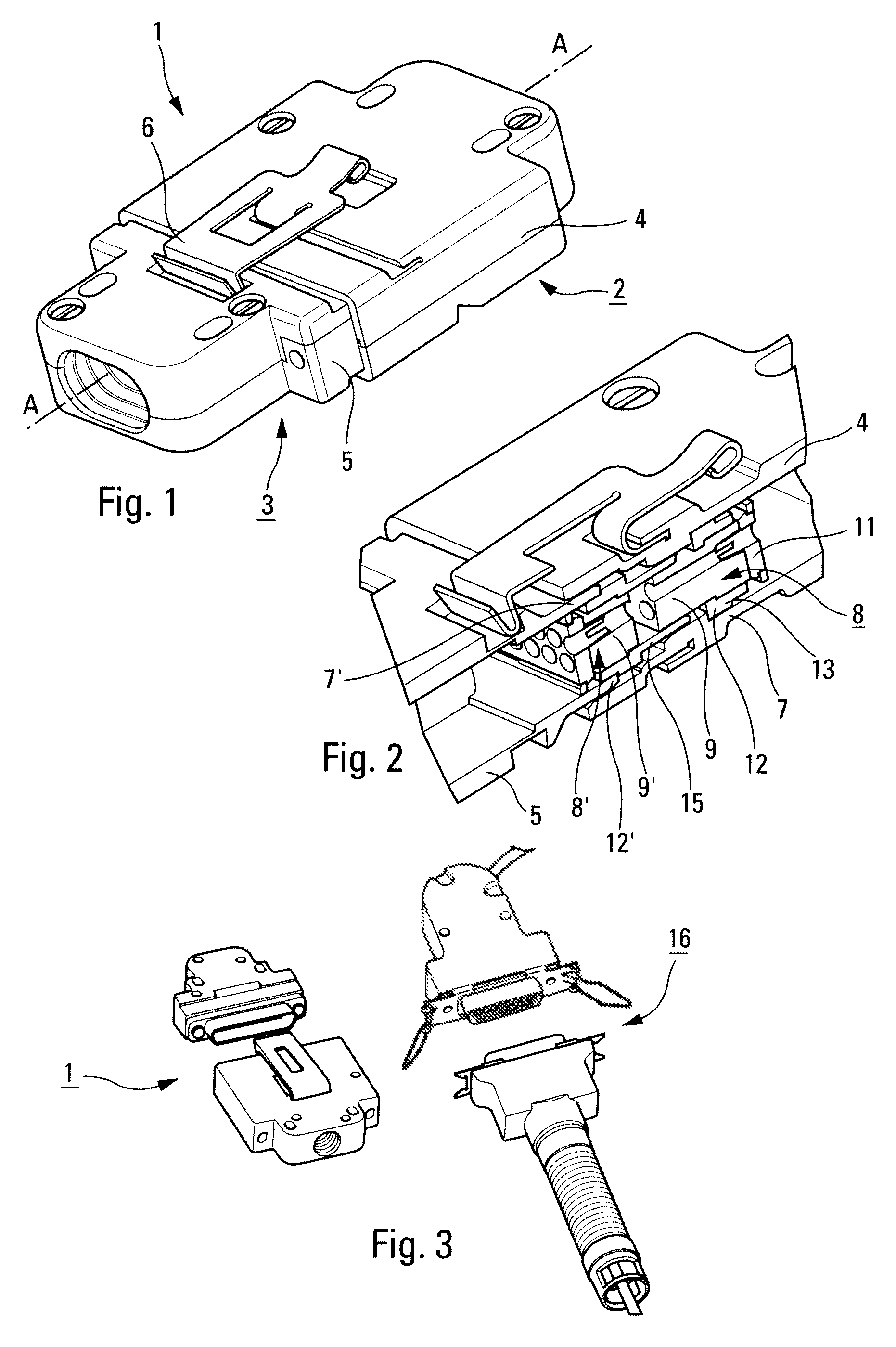
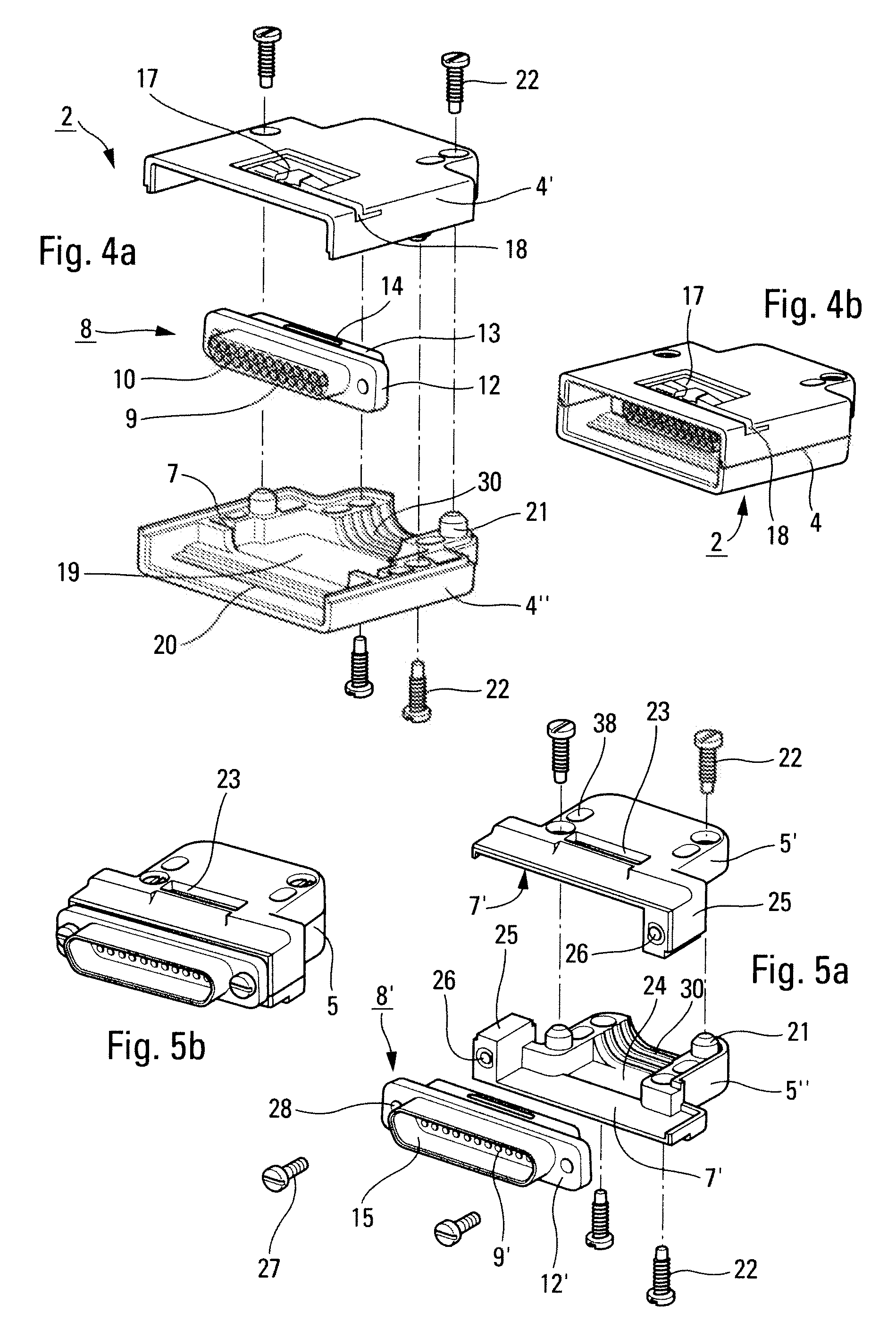
[0027]FIG. 1 shows a shielded sub-miniature connection assembly 1 consisting of two sub-miniature connectors 2, 3 comprising housings 4 and 5, consisting of two molded thermoplastic half-shells 4′-4″ and 5′-5″ coated with nickel protection and provided with complementary means of coupling such as a locking mechanism of the type of latch 6 and such as the means of guidance to make possible the assembly of the connector 2 and its complementary mating connector 3. The connectors 2 and 3 are likewise equipped with means of retaining contacts. These contacts, which are not shown, may be electrical copper or conducting alloy contacts, optical contacts, or an arrangement comprising different types of terminal.

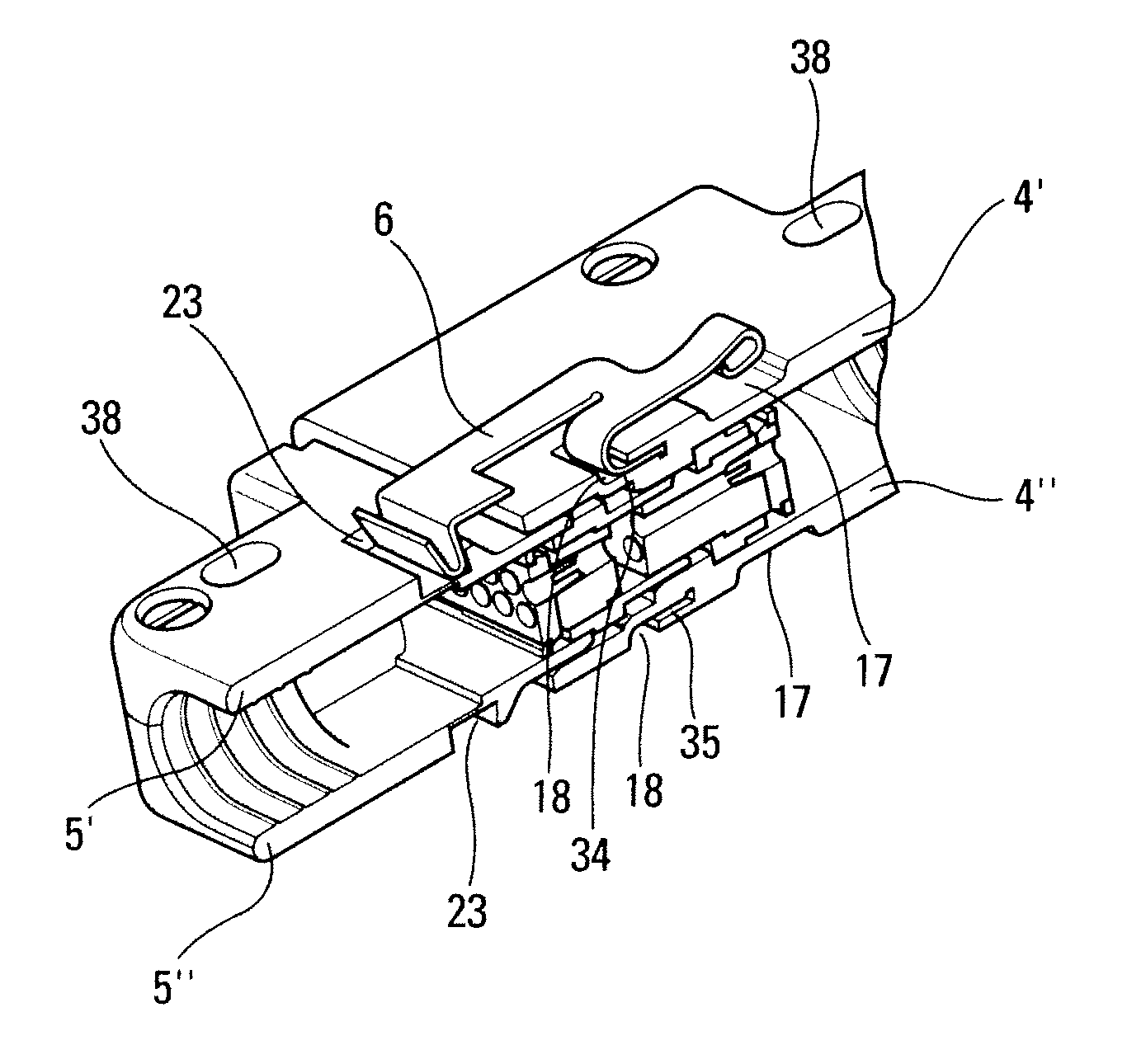
[0028]The contact-retaining and guidance means, making possible the coupling of the connectors, are shown in FIG. 2, which is a partial perspective section along line AA of FIG. 1.

[0029]On the one hand, the housing 4 of the connector 2 comprises a groove 7, whose section is suited to ...


PUM


Abstract

Locking device for a shielded sub-miniature connection assembly having two sub-miniature connectors with housings made of two molded thermoplastic half-shells, a high contact density miniature sub-assembly with a molded thermoplastic insulating body provided with contact cavities for the positioning and retention of contacts, wherein one of the housings includes on at least one of its faces a movable metal latch able to co-act with a slot made in at least one of the outside faces of the complementary housing.

Description

CROSS REFERENCE TO RELATED APPLICATION[0001]This application claims priority to French application number 0704272, filed Jun. 15, 2007, the disclosure of which is incorporated herein by reference in its entirety.BACKGROUND[0002]1. Field[0003]The aspects of the disclosed embodiments provide a shielded sub-miniature connection assembly and more particularly a connection assembly consisting of two sub-miniature connectors equipped with a locking device for locking the two sub-miniature connectors into a coupled position.[0004]The disclosed embodiments are directed to cable connectors in the field of data processing, of audio-visual communications, of telecommunications and more generally, in fields calling for the processing of multiple signals in a network.[0005]2. Brief Description of Related Developments[0006]In the field of shielded sub-miniature connectors, the utilization is known of an insulating body provided with contact cavities, making possible the positioning and retention ...

Claims


Application Information

Patent Timeline
Patent Type & Authority Patents(United States)
IPC IPC(8): H01R13/62
CPCH01R13/6272H01R13/6275H01R13/633H01R13/639
Inventor GERARD, PHILIPPEMALLET, PHILIPPE
Owner SOURIAU
Why Eureka
Try Eureka