
Pet crate

a technology for crate and animal, applied in the field of crate for animal, can solve the problems of cumbersome assembly of bolt and wing fasteners, difficulty in moving the apparatus, and difficulty in assembling bolts and wing fasteners, and achieve the effect of facilitating the movement of the apparatus

Inactive Publication Date: 2016-06-21
SWIFTIPET
View PDF25 Cites 22 Cited by
  • Summary
  • Abstract
  • Description
  • Claims
  • Application Information

AI Technical Summary

Benefits of technology

The patent describes a mechanism for securely closing a door. The mechanism includes a locking member and a release mechanism cover. The cover prevents the release mechanism from being accessed or the locking member from moving out of position. The mechanism also includes a modular door that can be easily secured in place and a handle for easy movement. The handle can be fixed or retractable and can be adjusted in length and angle for comfort and efficiency. The technical effect of the mechanism is a door that is secure, easy to operate, and comfortable to use.

Problems solved by technology

Crate assembly generally involves direct handling or manipulation of coupling structures including wing nut fasteners or snap type clips while balancing both crate halves and simultaneously assembling the door portion which is awkward and cumbersome because the top and bottom posts of the door must perfectly align with the holes on the top and bottom of the crate.
However, there are numerous fasteners to install requiring precision while using both hands.
The bolt and wing fasteners are cumbersome to assemble and the parts often get lost.
Snap fasteners are also a bit cumbersome to use as the snap can be difficult to close or open and the snap frame will at times detach from the crate frame.
Additionally, snap fasteners may become undone or break simply by bumping or dropping the crate.
Halves of known pet crate assemblies may become detached due to movement or vibrations that may loosen the securing devices.
Additionally, plastic pet crates do not have the capability to easily confine two animals separately and safely within one crate.

Method used


Image

  • Pet crate
  • Pet crate
  • Pet crate

Examples


Embodiment Construction

[0030]Although the following detailed description contains many specifics for the purposes of illustration, anyone of ordinary skill in the art will appreciate that many variations and alterations to the following details are within the scope of the invention. Accordingly, the following preferred embodiments of the invention are set forth without any loss of generality to, and without imposing limitations upon, the claimed invention.

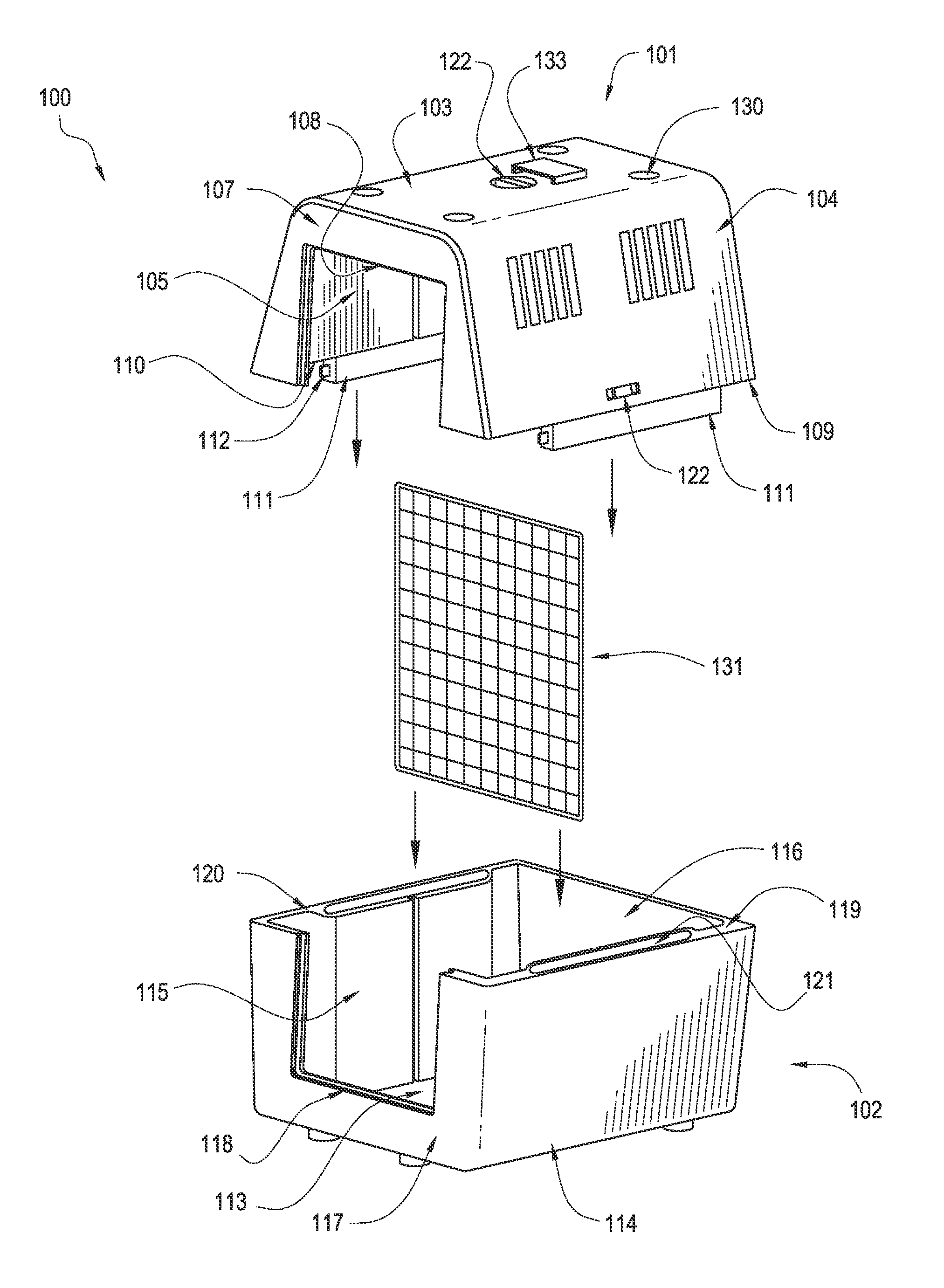
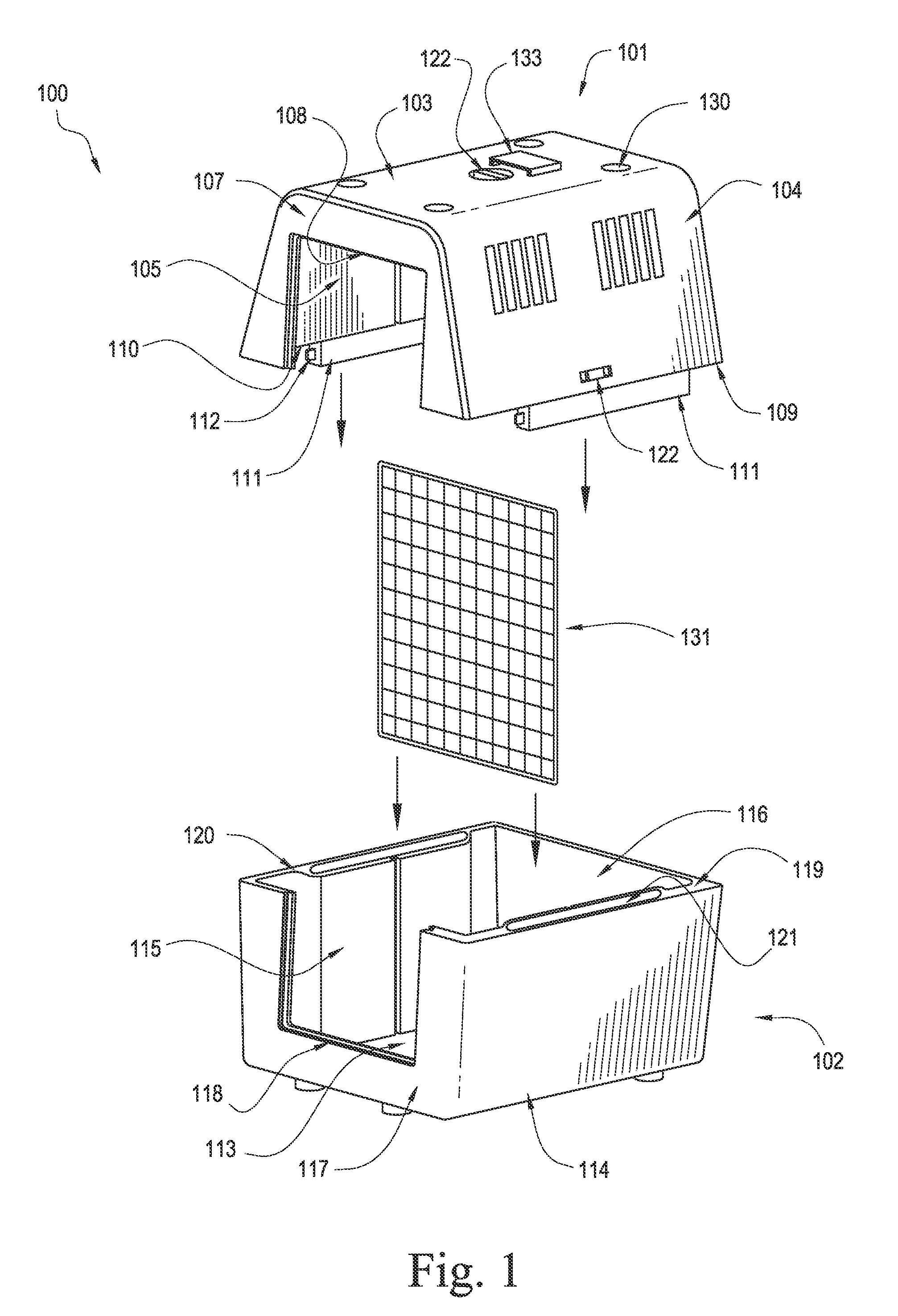
[0031]One embodiment of the pet crate 100 is depicted in FIG. 1. In this embodiment of the pet crate 100, the top portion 101 and the bottom portion 102 may be secured together to form a structure that provides temporary housing for a small animal.

[0032]The top portion 101 or the bottom portion 102 may be constructed with double walls for added strength, stability, or insulation. The top portion 101 or the bottom portion 102 may be a lightweight, plastic construction and may include openings for ventilation. The top portion 101 and the bottom portion 102...


PUM


Abstract

An apparatus for housing an animal includes a top portion wherein an upper flange is disposed along the lower edge of the bottom portion. A locking member is movably mounted to the upper flange. The apparatus may also include a bottom portion wherein a lower flange is disposed along the upper bottom edge of the bottom portion. The locking member engages with the lower flange when the locking member is in the outwardly extending locking orientation, which is at least partially defined by the locking member structured to engage at least a portion of the lower flange in an abutting relation to prevent detachment of the bottom portion from the top portion while disposed in the outwardly extending locking orientation. The apparatus may include a biasing mechanism structured to normally dispose and maintain the locking member in the outwardly extending locking orientation.

Description

CROSS REFERENCE TO RELATED APPLICATIONS[0001]Not applicable.STATEMENT REGARDING FEDERALLY SPONSORED RESEARCH OR DEVELOPMENT[0002]Not applicable.INCORPORATION-BY-REFERENCE OF MATERIAL SUBMITTED ON A COMPACT DISK[0003]Not applicable.BACKGROUND OF THE INVENTION[0004]1. Field of the Invention[0005]The present invention generally relates to an apparatus for housing an animal, more specifically, the present invention relates to an apparatus that can be easily assembled or disassembled and used for small animal transportation or housing.[0006]2. Background Art[0007]An area not currently addressed by pet crate manufacturers is the ability to quickly and easily assemble a pet crate while providing a safe pet confinement. In the majority of conventional or known crate assemblies, it is necessary for the pet owner to manually assemble a series of locking members while utilizing both hands. Crate assembly generally involves direct handling or manipulation of coupling structures including wing n...

Claims


Application Information

Patent Timeline
Patent Type & Authority Patents(United States)
IPC IPC(8): A01K1/03A01K1/02
CPCA01K1/0245A01K1/034
Inventor DE BIEN, HUMBERTO
Owner SWIFTIPET
Learn More