Mitral valve prosthesis delivery system

a technology for mitral valves and prostheses, which is applied in the field of percutaneous delivery and implantation of cardiac valve prostheses, can solve the problems of significant higher morbidity, affecting the quality of life of patients, and the damage of the valve too much to permit repair

Active Publication Date: 2018-09-13
MICOR LTD
View PDF1 Cites 29 Cited by
  • Summary
  • Abstract
  • Description
  • Claims
  • Application Information

AI Technical Summary

Benefits of technology

[0019]In some embodiments, the anchoring element can comprise an upper support and a lower support. The upper and lower supports can be coupled together by a flexible connector. The flexible connector can comprise a tubular skirt that can provide a seal and prevent regurgitation or leakage around the valve prosthesis.
[0027]In some embodiments, the coupler component can have a length 1 which allows the anchoring element to be serially displaced from the valve component when both the anchoring element and the valve component are in a collapsed configuration.
[0029]Accordingly, some embodiments can advantageously provide a seal for the prosthetic valve. For example, the skirt of some embodiments can provide a seal for the prosthetic valve without introducing a left ventricular outflow tract obstruction. The skirt can also prevent paravalvular leakage that can occur, in particular, at commissure locations. The skirt can also aid in ingrowth to enhance sealing.
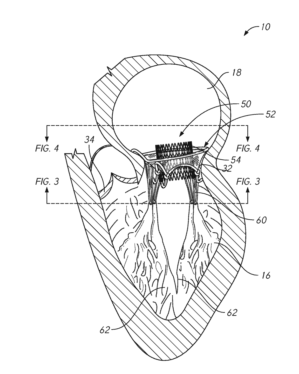
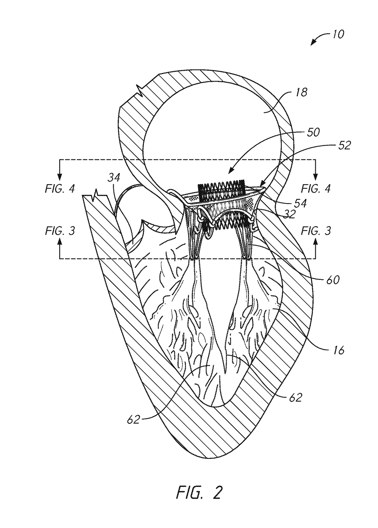
[0031]In accordance with some embodiments, the valve prosthesis can be delivered to the native mitral valve annulus in a collapsed configuration in which the valve component and anchoring element are serially (or longitudinally spaced relative to each other), rather than concentrically positioned relative to one another, thereby minimizing the diameter of the valve prosthesis and therefore, minimizing the diameter of the delivery system during delivery.
[0037]In some embodiments, the delivery system can further comprise a counter nose cone, wherein the counter nose cone can be positioned between the first and second sheaths. For example, the counter nose cone can maintain the position of the valve component within the first sheath or the second sheath prior to full release of the valve prosthesis.

Problems solved by technology

In many cases, however, the valve is too damaged to permit repair and the valve must be replaced with a prosthetic (artificial) valve.
While valve replacement surgery typically carries a 1-4% mortality risk in otherwise healthy persons, a significantly higher morbidity is associated to the procedure largely due to the necessity for extra-corporeal circulation.
Further, open-heart surgery is often poorly tolerated in elderly patients.
Transcatheter or percutaneous mitral valve replacement is particularly demanding technically, primarily due to the complex mitral valve and subvalvular anatomy, the absence well-structured implant site, the often multifactorial coinciding etiologies in mitral valve diseases, and the frequent occurrence of mitral valve annulus prolapse.
Current techniques of transcatheter mitral valve repair still have a high percentage of procedural failures or complications.
Their long-term efficiency is relatively low in particular because of a high rate of recurrent mitral regurgitation.
Significant challenges therefore remain for transcatheter mitral valve replacement and consequently and despite a particularly invasive side, surgical repair is the treatment usually recommended for diseases of the mitral valve.
Other limitations of the related art will become apparent to those of skill in the art upon a reading of the specification and a study of the drawings.

Method used


Image

  • Mitral valve prosthesis delivery system
  • Mitral valve prosthesis delivery system
  • Mitral valve prosthesis delivery system

Examples


Embodiment Construction

[0064]In the following detailed description, numerous specific details are set forth to provide a full understanding of the subject technology. It should be understood that the subject technology may be practiced without some of these specific details. In other instances, well-known structures and techniques have not been shown in detail so as not to obscure the subject technology.

[0065]Further, while the present disclosure sets forth specific details of various embodiments, it will be appreciated that the description is illustrative only and should not be construed in any way as limiting. Additionally, it is contemplated that although particular embodiments of the present disclosure may be disclosed or shown in the context of mitral valve prostheses, such embodiments may be used in other cardiac valve prosthesis applications. Furthermore, various applications of such embodiments and modifications thereto, which may occur to those who are skilled in the art, are also encompassed by ...


PUM


Abstract

A heart valve prosthesis delivery system can include a first sheath, a second sheath, a check valve, a check valve control lines, and a heart valve prosthesis carried within the first sheath or the second sheath. The check valve can be carried within the first sheath or the second sheath. The check valve has a check valve frame and a cover component, and the check valve control lines can be coupled to the check valve frame and configured to be manipulated by a physician to control release of the check valve. In use, the check valve can be configured to be deployed within the native valve structure for minimizing back flow of blood during placement of the valve prosthesis when the native valve leaflets are rendered non-functional by the presence of the delivery system.

Description

CROSS-REFERENCE TO RELATED APPLICATIONS[0001]This application is a continuation of U.S. application Ser. No. 15 / 344,486, filed Nov. 4, 2016, which claims the benefit of U.S. Provisional Application No. 62 / 252,390, filed Nov. 6, 2015, the entireties of each of which is incorporated herein by reference.BACKGROUNDField of the Inventions[0002]The present disclosure relates to devices and methods for the percutaneous delivery and implantation of a cardiac valve prosthesis. The valve prosthesis can be delivered in a collapsed state within a sheath to the valve and released in situ.Description of the Related Art[0003]The mitral valve, also referred to as the left atrioventricular or bicuspid valve, has two primary leaflets, the anterior and posterior leaflets, and a subvalvular apparatus consisting of chordae tendineae attaching to the anterior and posterior papillary muscles of the left ventricle. A healthy mitral valve allows blood to flow unimpeded from the left atrium to the left ventr...

Claims


Application Information

Patent Timeline
Patent Type & Authority Applications(United States)
IPC IPC(8): A61F2/24
CPCA61F2220/0008A61F2/2436A61F2250/0069A61F2/2409A61F2/2439A61F2/2418A61F2/2469A61F2/2412
Inventor ZHANG, JIWALSH, BRANDON G.YANG, CHENG Y.ZHU, JINHUA
Owner MICOR LTD
Why Eureka
Try Eureka