Bone Plate

a bone screw and bone screw technology, applied in the field of bone plates, can solve problems such as high stress, and achieve the effect of avoiding any undesirable effect on the compression ability of the non-threaded portion and increasing the angulation of the bone screw

Inactive Publication Date: 2011-12-01
DEPUY SYNTHES PROD INC
View PDF10 Cites 25 Cited by
  • Summary
  • Abstract
  • Description
  • Claims
  • Application Information

AI Technical Summary

Benefits of technology

[0009]According to one embodiment of the invention, the bone plate includes an upper surface, a bone contacting surface, and a plurality of holes extending through the upper and bone contacting surfaces. At least one of the holes is elongated in a direction substantially aligned with a longitudinal axis of the plate, and includes a threaded portion and a non-threaded portion. The threaded portion may extend over a range of greater than about 180° with respect to a central axis of the hole. The threaded portion of the hole is dimensioned and configured to engage a threaded head of a bone screw, and fix the bone screw at a predetermined angle with respect to the bone plate. Preferably, the threaded portion extends through the full thickness of the bone plate, i.e., from the upper surface to the bone contacting surface, thus maximizing the stability of the bone screw to bone plate interface.
[0010]With the threaded screw head fixed in the threaded portion of the elongated hole, the bone plate may be used as an internal fixative. Use in this configuration, however, creates high stresses at the interface of the bone plate and screw head because the plate is not forced against the bone, and therefore, the bone fracture is fixed primarily by friction between the plate and the bone. This increase in stress is taken into account by the threaded portion of the hole extending over a range of at least about 180° with respect to a central axis of the hole, and thereby enclosing the screw head in at least this angular range. This feature of the bone plate is especially advantageous where thin bone plates are involved. Preferably, the threaded portion is disposed on one of the two longitudinal ends of the hole. This positioning allows for the threaded portion to extend over a larger angular range. For example, the threaded portion may extend over a range of between about 190° and about 280°, and preferably over a range of between about 200° to 250°, thus maximizing the strength of the bone screw to bone plate interface.
[0014]According to another aspect of the present invention, at least one of the holes may be dimensioned and configured to receive a ball shaped head of a bone screw and provide for compression of two fractured bone fragments. For example, according to one embodiment, the non-threaded portion of the elongated hole, discussed above, may include a concave, substantially spherical recess at the upper surface. The recess may be dimensioned and configured to accommodate the spherical head of a conventional bone screw. Such an arrangement may be especially useful when the bone screw is put in place eccentrically with respect to the hole, as is necessary for attaining compression of a fracture. Additionally, the non-threaded portion of the hole may flare outward in the area of the bone contacting surface to provide for increased angulation of the bone screw with respect to the bone plate.
[0015]The threaded portion of the hole may be positioned closer to the end of the elongated hole that is closer to the center of the plate, thus avoiding any undesirable effects on the compression capability of the non-threaded portion. Thus, when the bone plate is used as a compression plate, the geometry of the non-threaded portion (compression portion) is not adversely affected by the presence of the threaded portion.

Problems solved by technology

Use in this configuration, however, creates high stresses at the interface of the bone plate and screw head because the plate is not forced against the bone, and therefore, the bone fracture is fixed primarily by friction between the plate and the bone.

Method used


Image

  • Bone Plate
  • Bone Plate
  • Bone Plate

Examples


Embodiment Construction

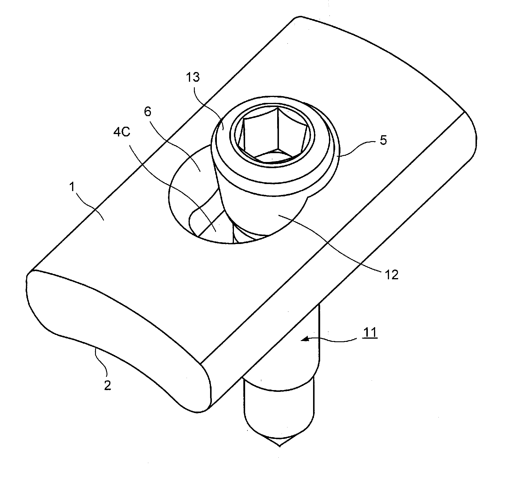
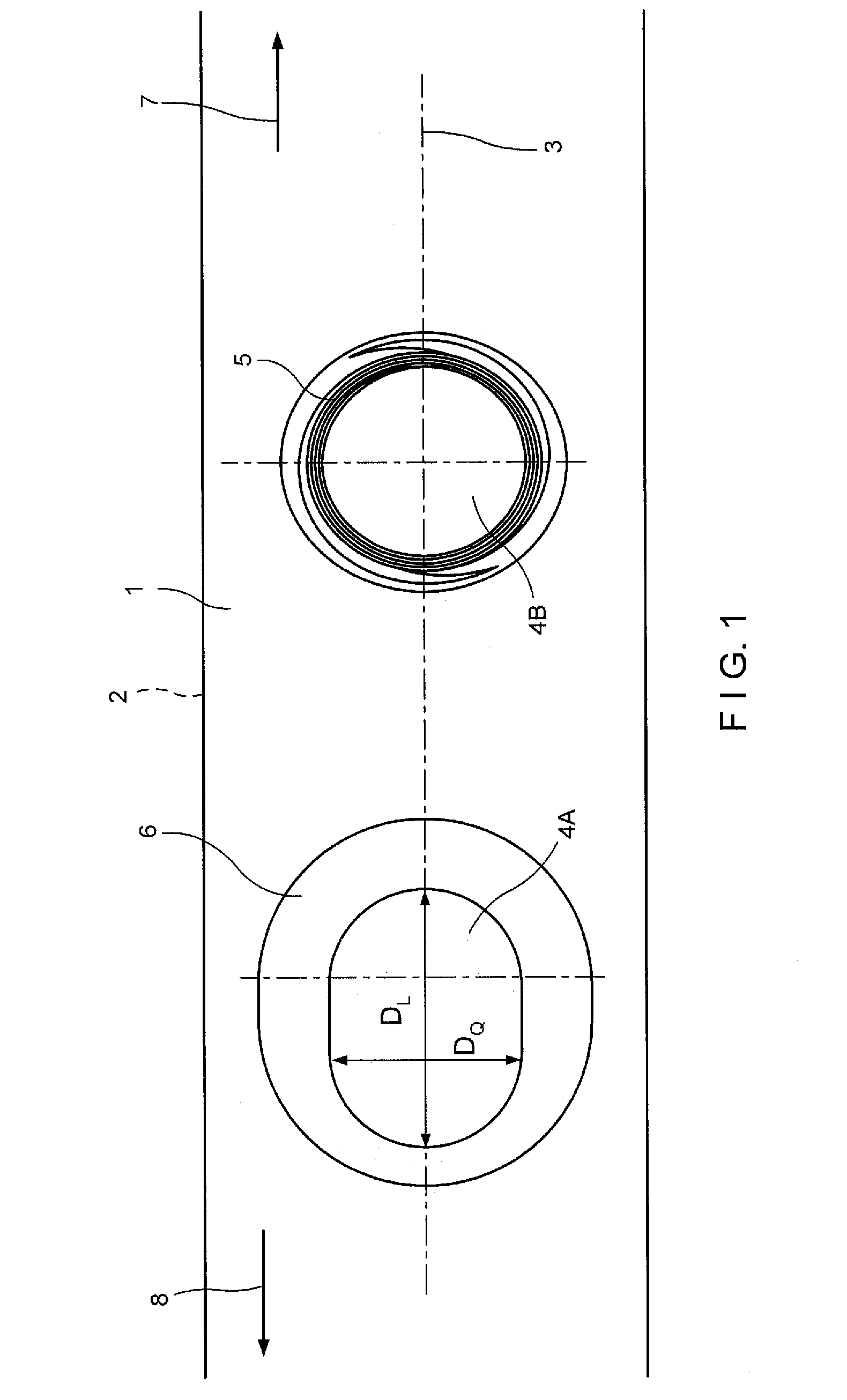
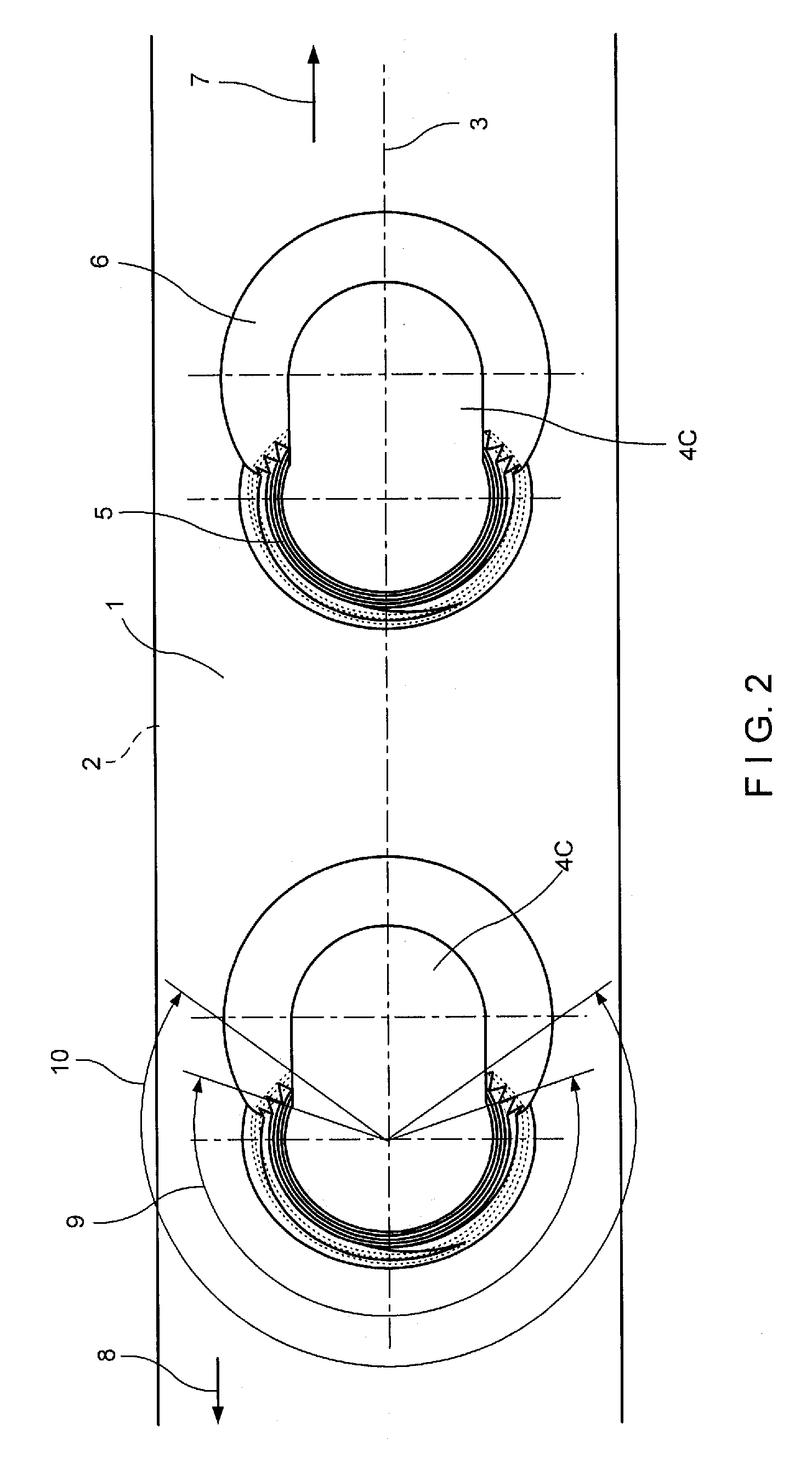
[0025]One embodiment of a bone plate according to the present invention is shown in FIG. 1. The bone plate includes an upper surface 1, a bone-contacting surface 2, and defines a longitudinal axis 3. The bone plate further includes two holes 4A and 4B, which are generally located along the longitudinal axis 3, and extend through the bone plate from upper surface 1 to bone-contacting surface 2. Holes 4A and 4B are dimensioned and configured to receive the heads of bone screws. As shown in FIG. 1, arrow 7 indicates a longitudinal direction toward one end of the bone plate and arrow 8 indicates a longitudinal direction toward a central portion of the bone plate.

[0026]Still referring to FIG. 1, hole 4A, which is located closer to the central portion of the bone plate, is elongated along the longitudinal axis 3 of the bone plate. More specifically, hole 4A defines first and second dimensions on bone-contacting surface 2. First dimension DL is substantially parallel to longitudinal axis 3...


PUM


Abstract

A bone plate includes an upper surface, a bone contacting surface, and at least one hole extending through the upper and bone contacting surfaces. The bone plate defines a longitudinal axis. The at least one hole defines a central axis and is elongated in a direction substantially aligned with the longitudinal axis. The hole may include a threaded portion and a non-threaded portion, and the threaded portion may extend through an angle of between about 190° and about 280° with respect to the central axis.

Description

CROSS-REFERENCE TO RELATED APPLICATIONS[0001]The present application is a continuation of U.S. patent application Ser. No. 09 / 946,974, which is a continuation-in-part of the U.S. National Stage designation of International Patent Application PCT / CH99 / 00106, filed Mar. 9, 1999 and the U.S. National Stage designation of International Patent Application PCT / CH99 / 00107, also filed Mar. 9, 1999. The entire content of both of these applications is expressly incorporated herein by reference thereto.FIELD OF THE INVENTION[0002]The present invention relates generally to devices for fixation of parts of a fractured bone and more specifically, to bone plates and systems for stabilization and / or compression of parts of a fractured bone.BACKGROUND OF THE INVENTION[0003]Bone plates may generally be utilized to carry out two different types of osteosynthesis, namely “rigid osteosynthesis” and “flexible osteosynthesis.” Rigid osteosynthesis is used for medical care of joint fractures, simple shaft ...

Claims


Application Information

Patent Timeline
Patent Type & Authority Applications(United States)
IPC IPC(8): A61B17/80A61B17/58
CPCA61B17/8057A61B17/8014
Inventor WAGNER, MICHAELFRIGG, ROBERTSCHAVAN, ROBERT
Owner DEPUY SYNTHES PROD INC
Why Eureka
Try Eureka