Method and System for Annotating Network Flow Information

a network flow and information technology, applied in the field of network flow information annotation, can solve the problems of limited flow information available from network devices, inability to provide real-time flow information, and inability to export flow information, so as to facilitate the creation of scalable flow monitoring solutions and low overhead

a network flow and information technology, applied in the field of network flow information annotation, can solve the problems of limited flow information available from network devices, inability to provide real-time flow information, and inability to export flow information, so as to facilitate the creation of scalable flow monitoring solutions and low overhead

US20090168648A1Inactive Publication Date: 2009-07-02ARBOR NETWORKS

Image

  • Method and System for Annotating Network Flow Information
  • Method and System for Annotating Network Flow Information
  • Method and System for Annotating Network Flow Information

Examples


Embodiment Construction

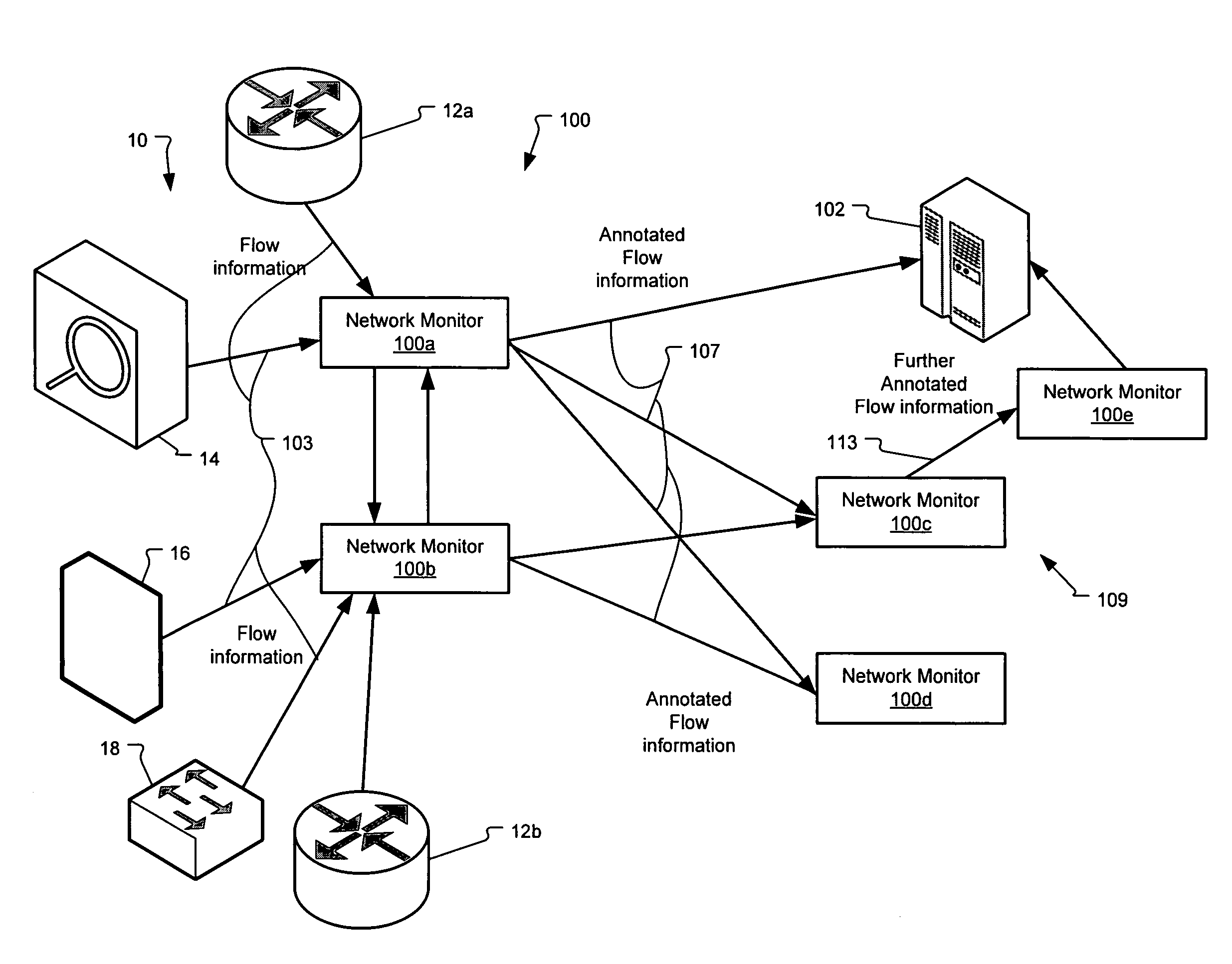
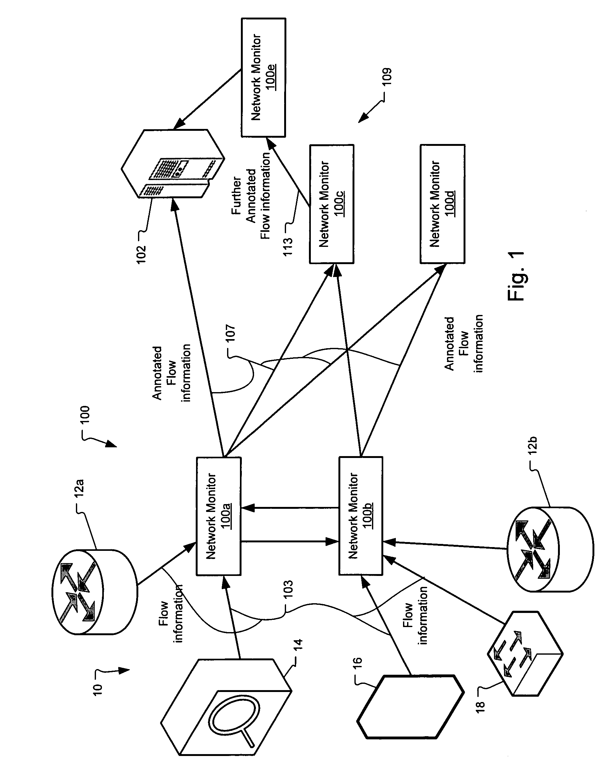
[0036]FIG. 1 is a block diagram of a flow annotation system 100 deployed within a network 10 according to the principles of the present invention.

[0037]In more detail, network communication devices such as routers 12a, 12b and / or switches 18 collect flow information from the packet information that is transmitted through the network 10 between other network communications devices, network nodes, and host computers. Flow information is also collected, in some examples from packet monitors or taps 14 that are installed usually solely to monitor packet traffic. An example here is the Netflow Analyzer offered by Cisco Systems, Inc. Other exemplary sources of flow information include network security devices, e.g., firewalls 16, that apply security policies and monitor for malicious code / packets.

[0038]The flow information 103 from these collectors is forwarded to one or more network monitors 100a, 100b. In some examples, these network monitors 100a, 100b and other network monitors in the...


PUM


Abstract

A scalable flow monitoring solution takes in standard flow records exported from network devices such as routers, switches, firewalls, hubs, etc., and annotates the flow with additional information. This information is derived from a number of sources, including Border Gateway Protocol (BGP), Simple Network Management Protocol (SNMP), user configuration, and other, intelligent flow analysis. These annotations add information to the flow data, and can be used to perform value-added flow analysis. The annotated flow is then resent to a configurable set of destinations using standard flow formatting, e.g., Cisco System Inc.'s NetFlow, in one implementation. This allows the annotated flow to be processed and the enhanced information to be used by other flow analysis tools and existing flow analysis infrastructure.

Description

BACKGROUND OF THE INVENTION[0001]Host computers, including servers and client computers, are typically interconnected to form computer networks. A computer network, and more generally a communications network, is a group of devices or network entities that are interconnected by one or more segments of transmission media on which communications are exchanged between those network entities. The communications can be transmitted electrically, including wireless links, or optically. The computer networks typically further comprise separate network communications devices, such as routers, switches, bridges, and hubs, for transmitting and relaying the communications between the network entities through the network's mesh.[0002]Computer networks are typically classified by their size or by the type of entity that owns the network. Often, business organizations maintain large computer networks. These computer networks are referred to as enterprise networks. Enterprise networks are typically...

Claims


Application Information

Patent Timeline
02 Jul 2009
Publication
US20090168648A1
IPC
H04L12/24
CPC
H04L12/2602; H04L41/12; H04L43/0876; H04L63/1408; H04L43/00; H04L43/026; Y02D30/50
Inventors
LABOVITZ, CRAIG; EGGLESTON, JOSEPH