Image pickup apparatus

a pickup apparatus and image technology, applied in the field of image pickup apparatus, can solve the problems of reducing the signal-to-noise ratio, affecting and causing light amount loss, so as to reduce the signal-to-noise ratio and improve the image quality of the picked-up imag

Inactive Publication Date: 2009-07-30
SONY CORP
View PDF6 Cites 94 Cited by
  • Summary
  • Abstract
  • Description
  • Claims
  • Application Information

AI Technical Summary

Benefits of technology

[0010]In the above-described “light field camera”, a microlens array is arranged in an image plane position of an image pickup lens, so the incident angle of a light ray with respect to a light-refracting configuration having a light-condensing property such as an on-chip lens configured on a light ray incident side of a solid-state image pickup device is largely different from that in the case of an image pickup apparatus in relat

Problems solved by technology

Therefore, as described above, in the case where a solid-state image pickup device in related art in which image height correction is performed is mounted in the “light field camera” directly or without any change

Method used


Image

  • Image pickup apparatus
  • Image pickup apparatus
  • Image pickup apparatus

Examples


first embodiment

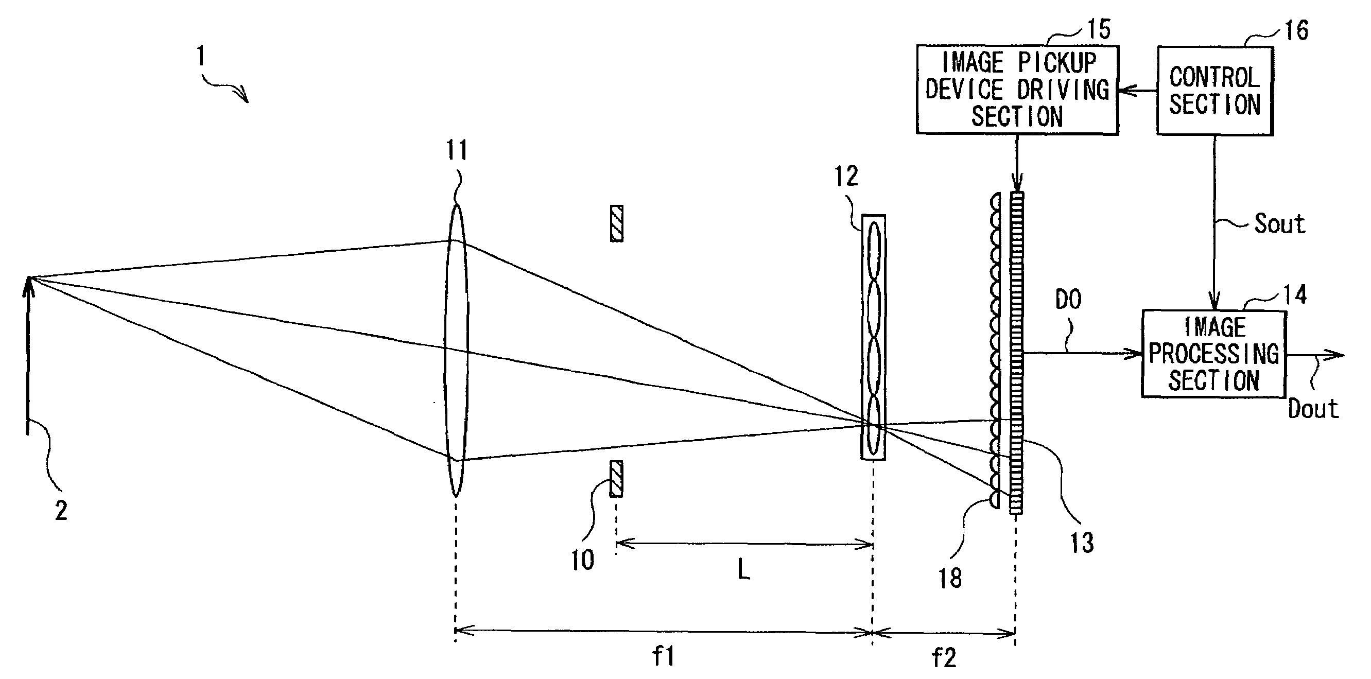
[0038]FIG. 1 illustrates the whole configuration of an image pickup apparatus (an image pickup apparatus 1) according to a first embodiment of the invention. The image pickup apparatus 1 picks up an image of an object 2 to output image pickup data Dout. The image pickup apparatus 1 includes an image pickup lens 11, an aperture stop 10, a microlens array 12, an on-chip lens 18 and an image pickup device 13 in order from a side closer to the object 2. The image pickup apparatus 1 also includes an image processing section 14, an image pickup device driving section 15 and a control section 16.

[0039]The image pickup lens 11 is a main lens for picking up an image of an object, and includes, for example, a typical image pickup lens used in a video camera, a still camera or the like.

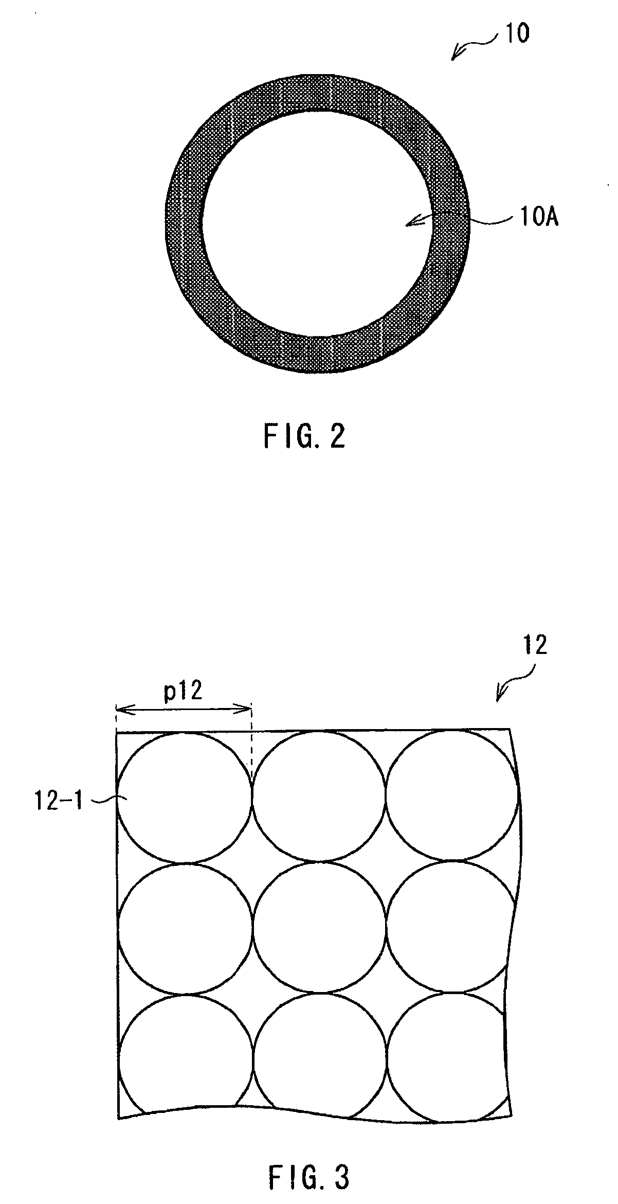
[0040]The aperture stop 10 is an optical aperture stop of the image pickup lens 11. For example, as illustrated in FIG. 2, the aperture stop 10 has one circular aperture section 10A in its central part. Thereby,...

second embodiment

[0078]Next, a second embodiment of the invention will be described below. Like components are denoted by like numerals as of the first embodiment, and will not be further described.

[0079]In the microlens array 12 according to the present embodiment, when the pitch between the microlenses 12-1 is “p12”, when the pixel size in a predetermined direction in an image pickup pixel (the pixel P which will be described later) of the image pickup device 13 is “s”, when the number of pixels P allocated to each microlens 12-1 in the predetermined direction is “m” (an integer), when a distance between the aperture stop 10 and the microlens array 12 as described above is “L”, and when the focal length of each of the microlenses 12-1 is “f2”, the pitch p12 between the microlenses 12-1 is represented by the following formula (11).

p12=(m×s)×{L / (L+f2)}  (11)

[0080]Now, referring to FIGS. 15 and 16, characteristic functions of the image pickup apparatus according to the present embodiment will be desc...

third embodiment

[0087]Next, the third embodiment of the invention will be described below. An image pickup apparatus according to the present embodiment has the same configuration as that of the image pickup apparatus according to the second embodiment, except that the image pickup apparatus includes an image processing section 14A which will be described below instead of the image processing section 14 of the image pickup apparatus according to the second embodiment, and that a microlens array (corresponding to the above-described microlens array 102) in which the pitch p12 between the microlenses 12-1 does not satisfy the above-described formula (11) is provided instead of the microlens array 12 described in the second embodiment. Therefore, like components are denoted by like numerals as of the second embodiment, and will not be further described.

[0088]FIG. 17 illustrates a functional block diagram of an image processing section (an image processing section 14A) used in the image pickup apparatu...


PUM


Abstract

An image pickup apparatus includes: an image pickup lens section; an image pickup device obtaining image pickup data on the basis of light detected; a microlens array section arranged on a focal plane of the image pickup lens section, and including a plurality of microlenses, each of the microlenses being provided corresponding to a plurality of image pickup pixels of the image pickup device; and a light-condensing section configured of a plurality of light-condensing elements, each of the light-condensing elements condensing light entering into each of the image pickup pixels of the image pickup device, wherein on the image pickup device, in a pixel region corresponding to each microlens, the pitch between the light-condensing elements is smaller than the pixel size, and in a boundary region between pixel regions corresponding to microlenses, respectively, the pitch between the light-condensing elements is larger than the pixel size.

Description

CROSS REFERENCES TO RELATED APPLICATIONS[0001]The present invention contains subject matter related to Japanese Patent Application JP 2008-016717 filed in the Japanese Patent Office on Jan. 28, 2008, the entire contents of which being incorporated herein by reference.BACKGROUND OF THE INVENTION[0002]1. Field of the Invention[0003]The present invention relates to an image pickup apparatus using a microlens array.[0004]2. Description of the Related Art[0005]Various image pickup apparatuses have been proposed and developed. Image pickup apparatuses performing predetermined image processing on image pickup data obtained by imaging or picking up an image to output the image pickup data have been proposed.[0006]For example, International Patent Publication No. 06 / 039486 and Ren.Ng, et al. “Light Field Photography with a Hand-Held Plenoptic Camera”, Stanford Tech Report CTSR 2005-02, propose image pickup apparatuses using a technique called “Light Field Photography”. Such an image pickup a...

Claims


Application Information

Patent Timeline
IPC IPC(8): H04N5/225H04N5/232
CPCG02B3/0056G02B3/0062H04N5/335H01L27/14627H04N5/2254H01L27/14625H04N25/00
Inventor ICHIMURA, ISAO
Owner SONY CORP
Why Eureka
Try Eureka